RDC-7
11
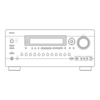
DISASSEMBLING PROCEDURES
Remove two screws A holding the top cover and bracket.
Remove six screws B holding the top cover and chassis.
Remove two screws C holding the top cover and the rear panel.
Lift up the top cover and remove it.
1. Top cover
2. Front panel assembly
Remove the top cover.
Disconnect two FFCs on the sockets of P7201B and P7202A.
Remove three screws D holding the front panel and chassis
from the top side.
Remove six screws E holding the front panel and chassis
from the bottom side.
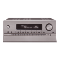
3. Bottom board
Remove four screws F holding the leg and chassis.
Remove twelve screws G holding the bottom board and chassis.
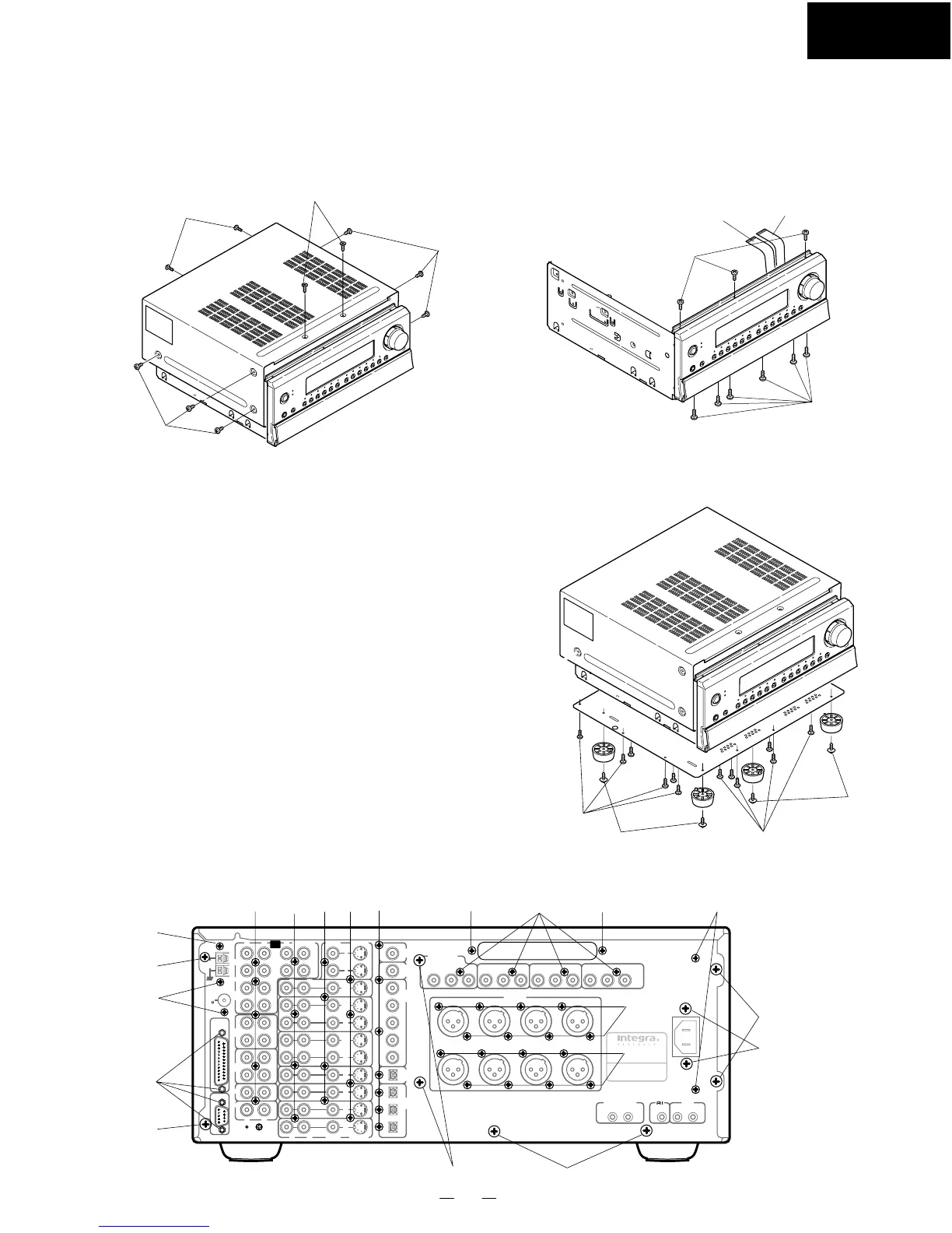
4. Rear panel
When PC board assembly are removed, remove the rear panel.
Remove the 8 screws
A
holding the rear panel and the chassis.
Remove the four special screws C.
Remove the 46 screws D to K.
Remove the two screws N.
A
B
C
D
E
F
G
H
I
J
K
L
M
N
: ATTB+8C(BC) (Part No.838440089) x 8 Chassis
: 3TTB+6B(BC) (Part No.838440068) x 3 Tuner unit
: Special screw (This screw is included to Terminal)
x 4 Multi channel input PC board
: 3TTB+8B(BC) (Part No.838430088) x 5 Input selector PC board
: 3TTB+8B(BC) (Part No.838430088) x 4 Input/Output terminal PC board
: 3TTB+8B(BC) (Part No.838430088) x 4 Video terminal PC board
: 3TTB+8B(BC) (Part No.838430088) x 4 S Video terminal PC board
: 3TTB+8B(BC) (Part No.838430088) x 7 DSP circuit terminal PC board
: 3TTB+8B(BC) (Part No.838430088) x 8 XLR jack PC board (1)
: 3TTB+8B(BC) (Part No.838430088) x 8 XLR jack PC board (2)
: 3TTB+8B(BC) (Part No.838430088) x 2 Primary circuit PC board
: 3TTB+8B(BC) (Part No.838430088) x 4 Component video PC board
: 3TTB+8B(BC) (Part No.838430088) x 2 Cover
: 3TTB+8B(BC) (Part No.838430088) x 2 Primary circuit PC board
C
B
A
B
D
E
P7202
P7201
F
F
G
G
DVD
VIDEO
5
VIDEO
4
VIDEO
3
ZONE 2
MONITOR
OUT
VIDEO
1
VIDEO
2
R
L
R
L
C
SUBWOOFER
IR IN
MAIN ZONE 2
VIDEO
S VIDEO
VIDEO
S VIDEO
INPUT 2
P
B
P
R
Y
INPUT 3
P
B
P
R
Y
OUTPUT
P
B
P
R
Y
OUT
OUT
IN
IN
IN
IN
IN
IN
AC
INLET
OUT
1
2
FM
ANT.
75
AM
ANT.
C
D
GND
MULTI
CHANNEL
INPUT
RS 232
TAPE
2
TAPE
1
FRONT
3
2
1
3
2
5
4
1
I
N
I
N
I
N
I
N
OUT
OUT
L
R
L
1
2
1
2
1
2
1
2
R
COMPONENT
VIDEO
INPUT 1
P
B
P
R
Y
DIGITAL
OUTPUT
(
COAXIAL
)
AC-3
RF
DIGITAL
INPUT
(
COAXIAL
)
DIGITAL
OUTPUT
(
OPTICAL
)
DIGITAL
INPUT
(
OPTICAL
)
PHONO
SURR
BACK
SURR
PRE
OUT
RIGHT CENTER SUBWOOFER
SURROUND
RIGHT
SURROUND
LEFT
SURROUND BACK
RIGHT
SURROUND BACK
LEFT
LEFT
PRE OUT
AV CONTROLLER
MODEL NO.
RDC-7
12V TRIGGER
AB
N
EFGH
L
I
J
K
MM
A
A
A
A
C
A
B
B
D
 Loading...