RDC-7
12
2
3
1
4
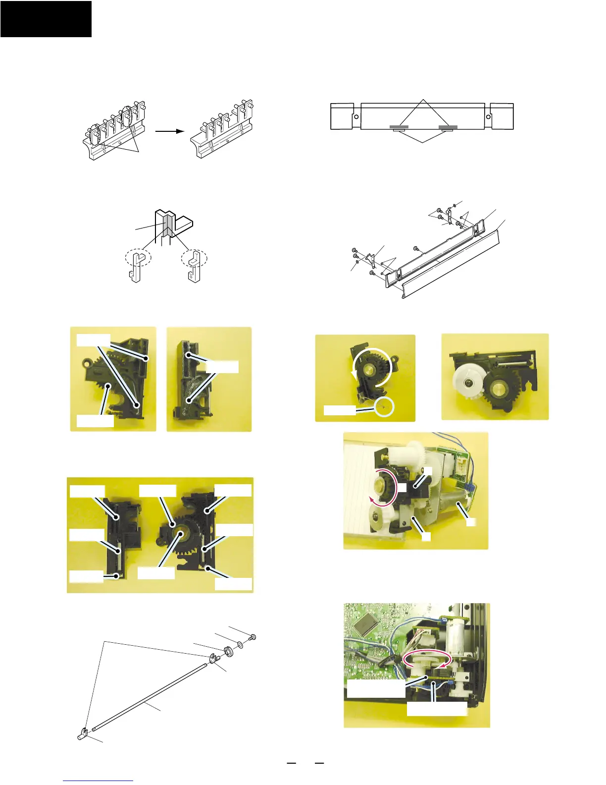
4. Attachment of shaft assembly
Apply Floil on the groove of holders.
Hang the spring from the down side of lever.
Attach the gear A to the holder R, and insert the
shaft A to fix the gear A.
Holder R Holder L
Gear A
Groove
Attach the gear S as shown
below.
Holder R
Spring
Lever
Shaft A
Gear A
Holder L
Spring
Lever
Insert the shaft to the shaft L and the shaft R.
Turn Gear A counter clockwise
fully.
Cross
1. Insert the retainer S.
2. Turn the gear A clockwise fully.
3. Insert the headphone jack to the front panel
4. Attach the motor assembly.
5. Attach the part above on the front panel.
Turn the gear clockwise fully and insert
the PC board ass'y (NAETC-6835)
Fix the PC board ass'y by the plastic rivet.
Plastic rivet
PC board ass'y
NAETC-6833
Groove
Shaft L
Shaft
Shaft R
Gear S
Retainer W
2.6TTS+6B(BC)
Apply floil
ASSEMBLING PROCEDURES
1. Attachment of door knob
When you replace the door knob assembly of lef side, cut the
two knobs below.
Cut
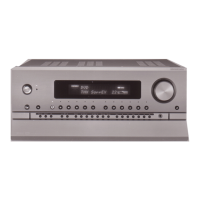
3. Attachment of door
Put the cushions according to the center of rib.
Inlay the door base to the door.
Put the five cushions on the door base.
Attach the stay L and stay R.
Put the spacers on the stay L and the stay R.
Cushion
Rib
3. Attachment of holders
Lever L
Lever R
Apply the floil G-902S (Part No.260447) on the lever
L and the lever R.
2
3
1
4
Cushion
Stay R
Spacer
Door
Door base
Cushion
Stay L
Spacer
53
53 : 2.6TTS+6B(BC)
Floil
Gear A
Groove
Holder R
Spring
Lever
Shaft A
Gear A
Holder L
Spring
Lever
Cross
Plastic rivet
PC board ass'y
NAETC-6833
Groove
 Loading...