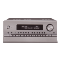
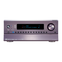
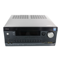
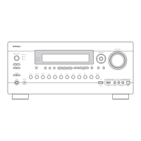
AV CONTROLLER
MODEL NO. RDC-7
12V TRIGGER
AB
Default setting
Input source Digital input Component video
CD COAXIAL 1
PHONO
FM
AM
TAPE 1 OPTICAL 1
TAPE 2 OPTICAL 2
DVD OPTICAL 3
COMPONENT VIDEO 1
VIDEO 1 ---- ----
VIDEO 2 COAXIAL 2
COMPONENT VIDEO 2
VIDEO 3 COAXIAL 3
COMPONENT VIDEO 3
VIDEO 4 COAXIAL 4 ----
VIDEO 5 COAXIAL 5 ----
DVD recorder
or other digital video
recording device
----
: No setting
: No applicable
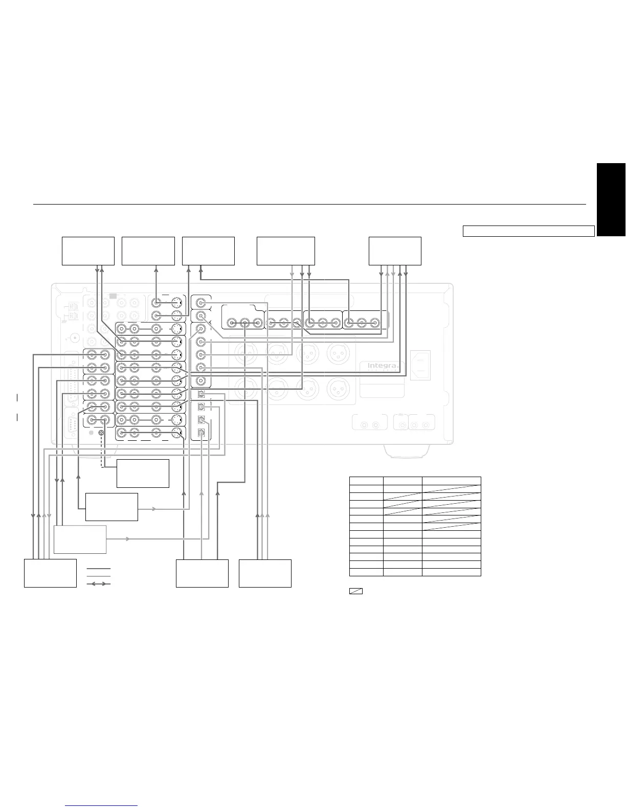
Standard connections
Here is explanation of how to connect the main
components to the RDC-7 in the standard manner.
There are many ways that any one component can be
connected, and it is up to you to decide which method
best fits your situation. The directions given here are
only one option and should only be thought of as such.
It is best to fully understand the nature of each
connector and terminal as well as each of your
components and their features to ascertain which
method of connection is best.
¥ Be sure to always refer to the instruction manual that
came with the component that you are connecting.
¥ Do not plug in the power cord until all connections
have been made.
¥ For input jacks, red connectors (marked R) are used
for the right channel, white connectors (marked L)
are used for the left channel, and yellow connectors
(marked V) are used for video connection.
¥ Insert all plugs and connectors securely. Improper
connections can result in noise, poor performance,
or damage to the equipment.
¥ Do not bind audio connection cables with power
cords and speaker cables. Doing so may adversely
affect the sound quality.
Connecting power amplifiers:
Speaker configuration and placement:
Radio antenna:
Enjoying the RDC-7 from a remote room (Zone 2):