RDC-7
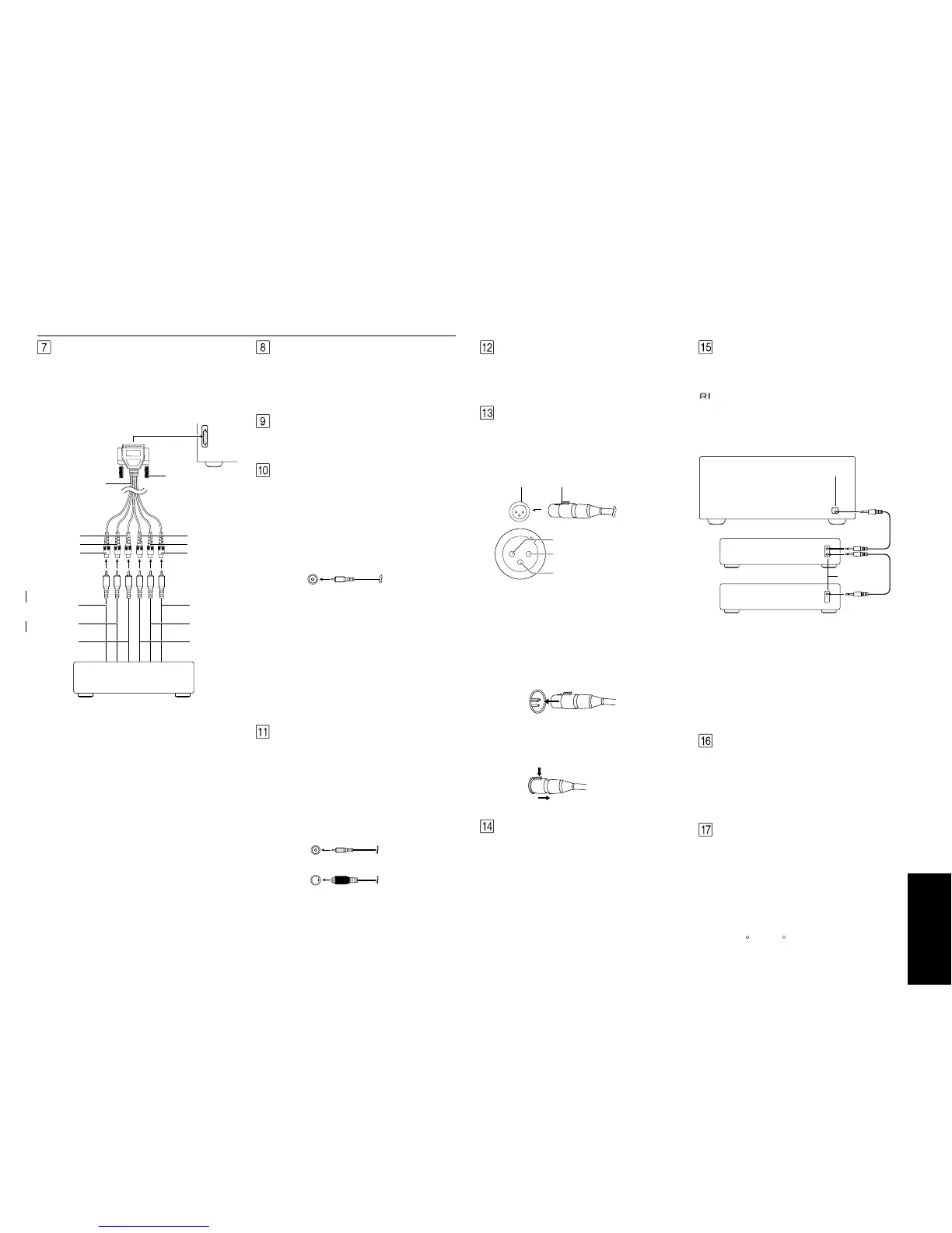
7
MULTI
CHANNEL
INPUT
(Green)
(Blue)
(Red)
(Brown)
(Black)
(Yellow)
Tighten locking
screws
Front left
DVD player or MPEG decoder
Front right
Center
Surround right
Surround left
Subwoofer
RDC-7 MULTI CHANNEL INPUT
(DB-25-type terminal)
DB-25 to
RCA 6-ch cable
(supplied)
Rear panel facilities
¥ When using the PHONO jacks, remove the caps that
cover then and store them safely where they will not
be lost. Whenever the PHONO jacks are not in use,
replace the caps on them.
¥ When connecting a VCR or other video compo-
nent, make sure you connect the audio and video
leads together (i.e., both to VIDEO 3).
¥ With LD players that have an AC-3RF terminal, con-
nect the audio source to the audio inputs of VIDEO
4 because only it supports the AC-3RF settings dur-
ing digital setup.
¥ The RDC-7 is designed for use with turntables that
use moving magnet cartridges.
MULTI CHANNEL INPUT
By connecting a DVD player, MPEG decoder, or other
component that has a multi channel port, you can
playback the audio with 5.1 channel or 7.1 channel
output. So, be sure to prepare a cable that can prop-
erly connect the RDC-7 to the peripheral device.
RS 232
The RS 232 port is to be used in conjunction with an ex-
ternal controller to control the operation of the RDC-7
by using an external device. The RS 232 port may also
be used in the future to update the operating software
of the RDC-7 so that it will be able to support new digi-
tal audio formats and the like as they are introduced.
GND
Use this GND terminal for connecting the ground (or
earth) wire if a turntable is connected.
AUDIO IN/OUT
These are the analog audio inputs and outputs. There
are 10 audio inputs (6 of which are linked to video in-
puts) and 4 audio outputs (2 of which are linked to
video outputs). The audio jacks are nominally labeled
for cassette tape decks, compact disc players, turn-
tables, and DVD players. To the audio jacks for VIDEO 1
to 5, connect the audio output from VCRs, LD players,
and other video components. The audio inputs and
outputs require RCA-type connectors.
The MULTI CHANNEL INPUT is a DB-25 port and the RDC-
7 is equipped provided with a DB-25-to-RCA 6-channel
cable. When making a multi-channel connection to a
DVD player or MPEG decoder, connect the DB-25 end
of the cable to the MULTI CHANNEL INPUT port on the
RDC-7 and RCA-type ends to the ends of the cables
connected to the other component. The channel col-
ors are shown below.
Front left (Blue)
Front right (Red)
Center (Green)
Surround left (Black)
Surround right (Yellow)
Subwoofer (Brown)
If the DVD player or MPEG decoder that you are con-
necting to is provided with DB-25-to-DB-25 cable, then
connect that directly to the RDC-7 and do not use the
cable supplied with the RDC-7.
When connecting the cable, be sure to secure the
locking screws on the DB-25 connectors.
VIDEO IN/OUT
These are the video inputs and outputs. There are 6
video inputs and 2 video outputs and each one in-
cludes both composite video and S-video configura-
tions. Connect VCRs, LD players, DVD players, and
other video components to the video inputs. S-video
sources can be viewed via the S-video or composite
outputs, while composite sources can only be viewed
through the composite output.
The 2 video output channels can be used to be con-
nected to video tape recorders for making recordings.
Composite video jack
S video jack
¥ When connecting a VCR or other video compo-
nent, make sure you connect the audio and video
leads together (i.e., both to VIDEO 3).
¥ With LD players that have an AC-3RF terminal, con-
nect the video source to the video inputs of VIDEO 4
because only it supports the AC-3RF settings during
digital setup.
RCA type
IR IN MAIN
If the RDC-7 is located inside a rack or cabinet that will
not allow infrared beams to reach the IR sensor, you will
need to connect a remote sensor* to this input to be
able to use the remote controller. Then install the re-
mote sensor in an unblocked location where you can
easily point the remote controller.
* An optional remote sensor kit is required.
IR IN ZONE 2
This jack allows you to connect a multiroom system kit
so that you can use the remote controller while you are
in the remote zone (Zone 2), which may be far sepa-
rated from the RDC-7.
* To be able to use the remote controller in the remote
zone (Zone 2), you must connect one of the follow-
ing (sold separately):
¥ IntegraÕs Multi-Room System Kit (IR Remote Control-
ler Extension System).
¥ A multiroom A/V distribution and control system
from Niles , Xantech , or the like.
ZONE 2
These are the audio and video output jacks for the re-
mote zone (Zone 2). Use these outputs to connect the
remote zone.
PRE OUT (Balanced type)
These jacks are for connecting power amplifiers. If the
jacks on your power amplifier are XLR (balanced) type
jacks, connect them here. The pin assignments for
these terminals are shown below.
12V TRIGGER
This is a 12-volt output terminal so that the RDC-7 can
control other external devices. For other devices that
have an input terminal of the same kind, you can con-
nect it to this terminal with 1/8-inch mini-jack cable so
that its power is turned on when you press an input
source button. The RDC-7 is equipped with two 12-volt
trigger terminals and each supplies a current of 100
mA. When you connect to either of these terminals,
make the appropriate settings in the OSD menu.The ini-
tial settings are ÒA: OnÓ and ÒB: Off,Ó so if you are only
connecting to A, these settings will not need to be
changed.
(RI)
By connecting the connector as shown in the dia-
gram below, you can use the RC-418M remote control-
ler to operate Integra/Onkyo cassette tape decks and
compact disc players that also have Integra/OnkyoÕs
connectors. Simply connect a remote control cable
from this connector to the connector of the cas-
sette tape deck or compact disc player. An remote
control cable with a 3.5-mm (1/8-inch) miniature two-
conductor plug comes with every cassette tape deck
and compact disc player that has an connector.
¥ For remote control operation, the audio connection
cables must also be connected.
¥ The RC-418M remote controller does not support
turntables.
¥ If the connected component has two connec-
tors, you can use either one to connect to the RDC-
7. The other one can be used to daisy chain with
another component.
¥ For Integra DVD or MD players, you can control
them by simply pointing the RC-418M controller di-
rectly at the component.
Ex:Integra/Onkyo
CD player
Ex:Onkyo
Cassette tape deck
RDC-7
connector
connector
These pin assignments conform to the standards made
by the Audio Engineering Society. Check the instruc-
tion manual that came with your power amplifier and
verify that the input pin assignments are compatible
with those for the RDC-7.
1. GND
Balanced cableXLR type
2. non-inverting (+)
3. inverting (-)
1. Connecting the output terminal
Match the pins and insert the terminal until you hear a
Òclick. Ó Ensure that it is secure by gently pulling it.
2. Disconnecting tha output terminal
Pull out the cable (in the direction indicated by the
arrow) while holding down the connection cable button.
Push
These outputs are activated by the Zone 2
button on
the front panel.
R
R
RI
RI
RI
RI
RI
RI
RI
RI
 Loading...