
Do you have a question about the Intel D915GVWB and is the answer not in the manual?
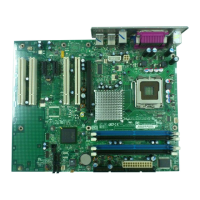
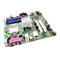
| Form Factor | Micro ATX |
|---|---|
| Socket Type | LGA 775 |
| Memory Slots | 2 |
| Maximum Memory | 2 GB |
| Onboard Video | Intel Graphics Media Accelerator 900 |
| LAN | 10/100 Mbps Ethernet |
| IDE | 1 x ATA 100 |
| BIOS | AMI BIOS |
| Supported CPU | Intel Pentium 4, Intel Celeron D |
| Memory Type | DDR |
| USB Ports | 8 x USB 2.0 (4 rear, 4 via headers) |
| Storage Interfaces | ATA-100, SATA-150 |
| Chipset | Intel 915GV Express Chipset |
Specifies available configurations for board production and market.
Lists compatible operating systems for the desktop board.
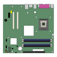
Identifies and locates major components on the desktop board.
Details processor support and installation requirements for the LGA775 package.
Describes memory support, including DDR SDRAM DIMM sockets and capacity.
Lists the devices comprising the Intel 915GV Express Chipset.
Outlines the graphics capabilities, including the Intel 915GV Express Chipset.
Details the 6-channel audio subsystem features and connectors.
Explains the features of the super I/O controller.
Describes the optional Fast PCI LAN subsystem features.
Covers the desktop board's support for up to eight USB 2.0 ports.
Explains the IDE interface capabilities for connecting drives.
Details the four Serial ATA channels supported by the board.
Lists the available expansion slots for add-in cards.
Provides information on the BIOS functions, setup, and auto-configuration utilities.
Details power management implementation and hardware support.
Explains entering the ACPI S3 sleep state for quick system resume.
Describes resuming operation from ACPI S1 or S3 state via modem.
Covers waking the computer from an ACPI S1 or S3 state using USB activity.
Explains waking the computer from an ACPI S1 or S3 state via PS/2 devices.
Details waking the computer from ACPI S1, S3, or S5 states via PME# signal.
Notes the presence of a speaker for beep code error reporting.
Mentions the battery for CMOS RAM and clock functions.
Describes the time-of-day clock and 100-year calendar.
Provides essential precautions and guidelines before starting installation procedures.
Lists safety measures to avoid injury during installation.
Offers guidelines for safe and compliant board installation.
Stresses the importance of EMC compliance for components and the system.
Explains the necessity of certified chassis and components for safety and compliance.
Advises against overloading the power supply output.
Highlights the requirement for battery safety markings on the chassis.
Defines the evaluated use of Intel desktop boards as Information Technology Equipment.
Provides instructions on how to install the I/O shield for RF shielding and dust protection.
Details the procedure for installing and removing the desktop board from the chassis.
Covers the steps for installing and removing the processor.
Step-by-step guide for safely installing a processor into the socket.
Explains how to attach the processor fan heat sink to the retention mechanism.
Guides on connecting the processor fan cable to the motherboard header.
Provides instructions on removing the processor fan heat sink and processor.
Covers procedures for installing and removing memory modules (DIMMs).
Step-by-step instructions for inserting DIMMs into the sockets.
Step-by-step instructions for removing DIMMs from the sockets.
Details how to connect the IDE cable to drives and the motherboard.
Provides instructions for connecting the SATA cable to drives and the motherboard.
Shows the location and pin assignments for internal motherboard headers.
Explains connecting USB 2.0 devices to internal headers.
Details connecting front panel components like power buttons and LEDs.
Describes connecting front panel audio devices.
Guides on connecting speakers to the back panel audio connectors.
Covers connecting fan and power cables to the motherboard.
Details connecting fan cables to the motherboard fan headers.
Provides instructions for connecting main power and CPU power cables.
Explains connecting 2x10 power supplies to the 2x12 main power connector.
Details connecting 2x12 power supplies to the motherboard.
Locates and identifies other peripheral interface connectors.
Explains how to set jumpers for BIOS configuration modes.
Provides steps to clear BIOS passwords using the configuration jumper.
Shows the location of the various connectors on the back panel.
Guides on how to safely replace the coin-cell battery.
Instructions for updating BIOS via Windows using the Express utility.
Steps for updating BIOS using a bootable diskette or other media.
How to download the necessary BIOS update files.
General procedures and cautions for updating the system BIOS.
Steps to recover the BIOS in case of a failed update.
Explains diagnostic beep codes issued by the BIOS during POST.
Lists and explains error messages displayed by the BIOS during POST.
Lists the safety standards the desktop board complies with.
Declares conformity to EU directives for EMC and Low Voltage.
Provides information on disposal and recycling of product components.
Lists EMC regulations the desktop board complies with.
Shows and explains the various product certification marks on the board.