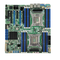
Intel® Server Board S2600CO Family TPS Table of Contents
Revision 1.4
Intel order number G42278-004
v
7.2.1 Availability ................................................................................................................ 81
7.2.2 Network Port Usage ................................................................................................ 81
8. On-board Connector/Header Overview ............................................................................. 82
8.1 Power Connectors ................................................................................................... 82
8.1.1 Main Power .............................................................................................................. 82
8.1.2 CPU Power Connectors .......................................................................................... 82
8.1.3 PCIe Card Power Connectors ................................................................................. 83
8.2 Front Panel Headers and Connectors .................................................................... 83
8.2.1 SSI Front Panel Header .......................................................................................... 83
8.2.2 Front Panel USB Connector ................................................................................... 87
8.2.3 Intel
®
Local Control Panel Connector ..................................................................... 87
8.3 On-Board Storage Connectors ............................................................................... 87
8.3.1 SATA Only Connectors: 6 Gbps ............................................................................. 88
8.3.2 SATA/SAS Connectors ........................................................................................... 88
8.3.3 SAS SGPIO Connectors ......................................................................................... 88
8.3.4 Intel
®
RAID C600 Upgrade Key Connector ............................................................ 88
8.3.5 HSBP_I
2
C Header ................................................................................................... 89
8.3.6 HDD LED Header .................................................................................................... 89
8.3.7 Internal Type-A USB Connector ............................................................................. 89
8.3.8 Internal 2mm Low Profile eUSB SSD Connector ................................................... 89
8.4 Management and Security Connectors .................................................................. 90
8.4.1 RMM4_Lite Connector ............................................................................................ 90
8.4.2 RMM4_NIC connector ............................................................................................. 90
8.4.3 TPM Connector ....................................................................................................... 90
8.4.4 PMBus* Connector .................................................................................................. 91
8.4.5 Chassis Intrustion Header ....................................................................................... 91
8.4.6 IPMB Connector ...................................................................................................... 91
8.5 Fan Connectors ....................................................................................................... 91
8.5.1 System FAN Connectors ......................................................................................... 92
8.5.2 CPU FAN Connector ............................................................................................... 92
8.6 Serial Port Connectors ............................................................................................ 92
8.6.1 Serial Port A connector (DB9) ................................................................................. 92
8.6.2 Serial Port B Connector .......................................................................................... 93
8.6.3 Video Connector ...................................................................................................... 93
8.7 Other Connectors and Headers .............................................................................. 94
8.7.1 FAN BOARD_I
2
C Connector ................................................................................... 94
8.7.2 IEEE 1394b Connector ........................................................................................... 94
9. Reset and Recovery Jumpers ............................................................................................ 95
9.1 BIOS Default (that is, CMOS Clear) and Password Reset Usage Procedure ....... 96
9.1.1 Set BIOS to default (that is, Clearing the CMOS) .................................................. 96
9.1.2 Clearing the Password ............................................................................................ 96
 Loading...
