Intel® Server Board S2600CO Family TPS On-board Connector/Header Overview
Revision 1.4
Intel order number G42278-004
87
Color State Criticality Description
Both uBoot BMC FW images are bad. (Chassis ID shows
blue/solid-on for this condition)
240VA fault
Fatal Error in processor initialization:
Processor family not identical
Processor model not identical
Processor core/thread counts not identical
Processor cache size not identical
Unable to synchronize processor frequency
Unable to synchronize QPI link frequency
8.2.2 Front Panel USB Connector
The server board includes a 10-pin connector, that when cabled, can provide up to two USB
ports to a front panel. On the server board the connector is labeled “USB5-6”. The following
table provides the connector pin-out.
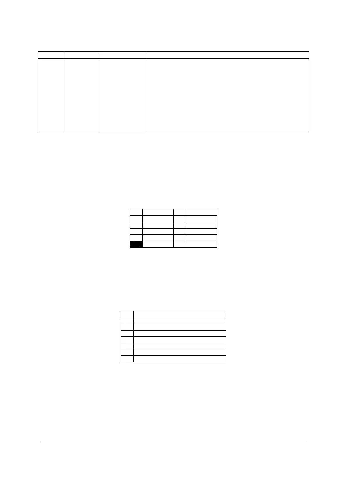
Table 30. Front Panel USB Connector Pin-out (USB5-6)
Pin Signal Name
Pin
Signal Name
1 +5V 2 +5V
3 USB_N 4 USB_N
5 USB_P 6 USB_P
7 GND 8 GND
10
8.2.3 Intel
®
Local Control Panel Connector
The server board includes a 7-pin connector that is used when the system is configured with
Intel
®
Local Control Panel with LCD support. On the server board this connector is labeled
LCPand is located on the front edge of the board. The following table provides the pin-out for
this connector.
Table 31. Intel
®
Local Control Pane Connector Pin-out (LCP)
Pin Signal Name
1 SMB_SENSOR_3V3STBY_DATA_R0
2 GROUND
3 SMB_SENSOR_3V3STBY_CLK
4 P3V3_AUX
5 FM_LCP_ENTER_N_R
6 FM_LCP_LEFT_N_R
7 FM_LCP_RIGHT_N_R
8.3 On-Board Storage Connectors
The server board provides connectors for support of several storage device options. This
section provides a functional overview and pin-out of each connector.

 Loading...


