Intel® Server Board S3420GP User Guide 45
Note: Make sure the alignment triangle mark and the alignment triangle cutout align correctly.
To assist in package orientation and alignment with the socket:
Installing the Heatsink(s)
1. If a protective film covers the thermal interface material (TIM) on the underside of
the heatsink, remove the protective film.
2. Align heatsink fins to the front and back of the chassis for correct airflow. Airflow
goes from front-to-back of chassis.
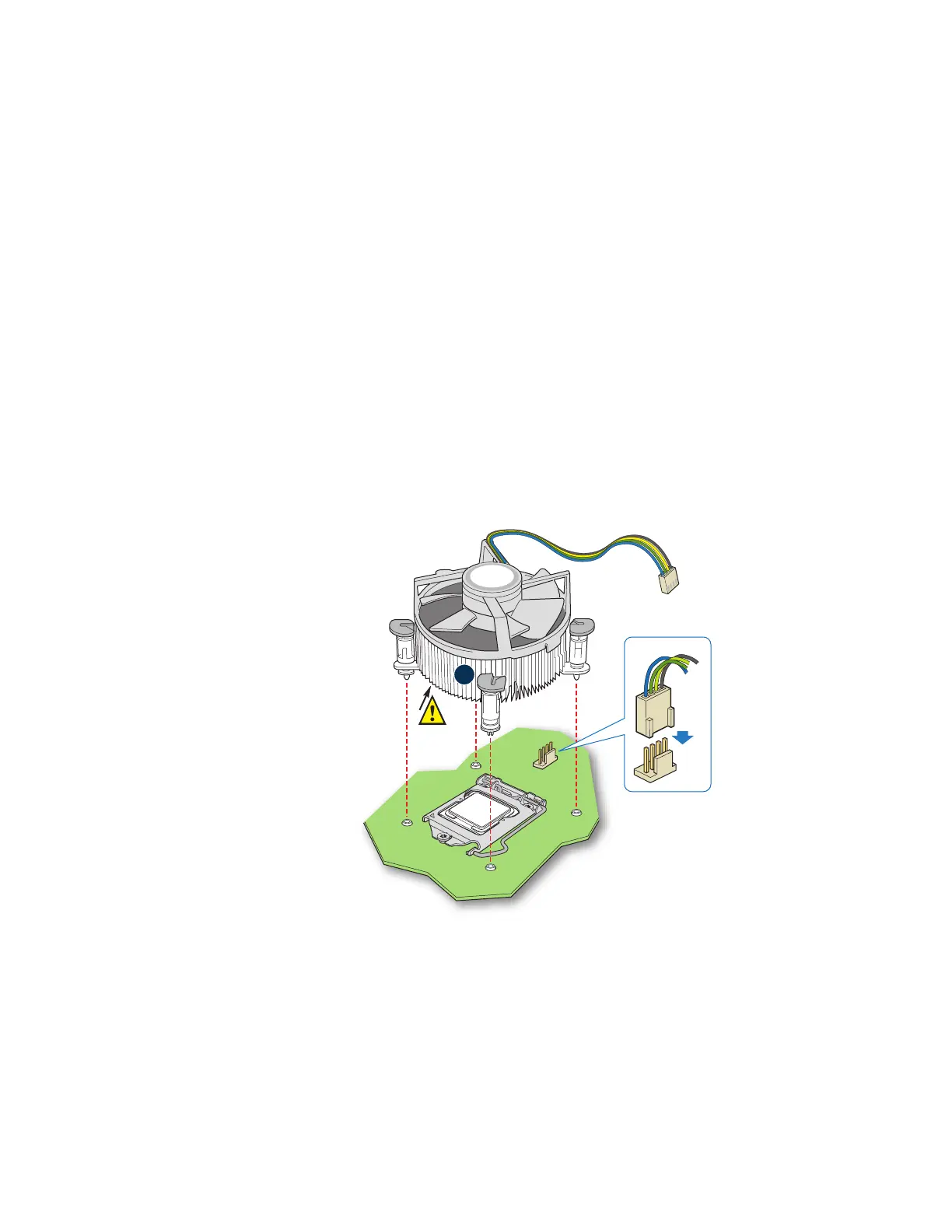
3. Each heatsink has four captive fasteners and should be tightened as shown.
4. Using a #2 Phillips* screwdriver, finger-tighten each fastener diagonally, according
to the white-circled numbers.
5. Securely re-tighten each fastener again in the same order as performed in Step 4.
6. Attach fan power cable to server board as shown.
Figure 17. 2U Reference Heatsink Assembly
7. Reinstall and reconnect any parts you removed or disconnected to reach the
processor sockets.
8. Replace the server's cover and reconnect the AC power cord. Refer to the
documentation that came with your server chassis for instructions on installing the
server's cover.
Note: Heatsink
styles may vary
TIM
A

 Loading...


