Description 9
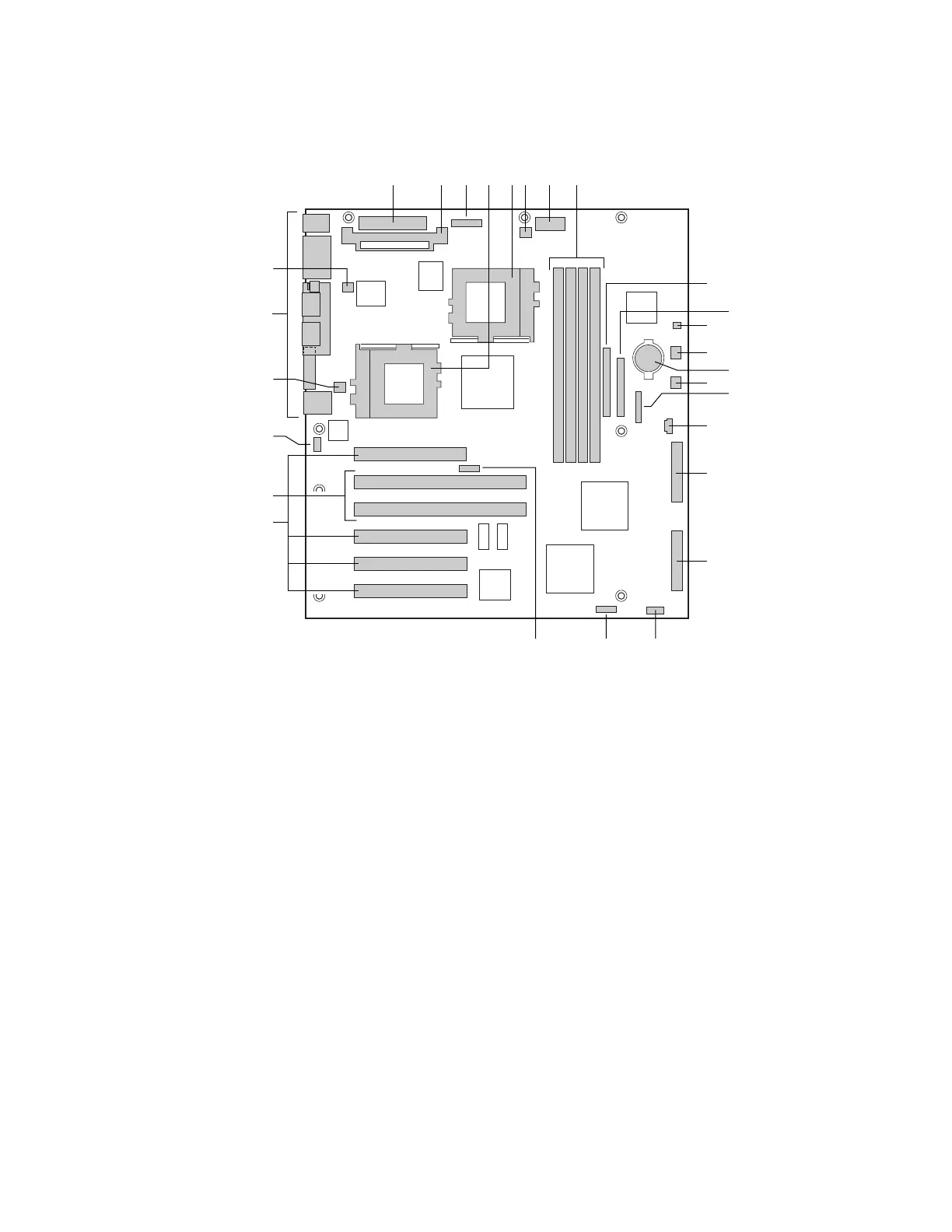
Server Board Connector and Component Locations
OM10670
T S
R
N
Q
P
O
M
J
I
K
L
X
AA
Z
U
G
FCADB E H
Y
W
V
A. Main power connector (P33)
B. VRM socket (P32)
C. Auxiliary power connector (P34)
D. Primary processor (P13)
E. Secondary processor (P14)
F. Secondary processor heatsink
fan connector (P36)
G. Power supply signal connector
(P37)
H. DIMM slots (P15-P18)
I. IDE connector (P19)
J. Floppy drive connector (P20)
K. Two pin speaker connector
(P31)
L. System fan connector FAN3A
(P29)
M. Battery
N. System fan connector FAN2A (P27)
O. Front panel connector(P23)
P. Four pin speaker connector (P25)
Q. Ultra Single Ended (SE) SCSI connector
(P9)
R. Ultra160 LVD SCSI connector (P8)
S. Configuration jumper block (1L4)
T. Configuration jumper block (1J15)
U. CPU speed jumper block (5E1)
V. 33 MHz/32-bit PCI connectors
W. 66 MHz/64-bit PCI connectors
X. Chassis intrusion connector (pins 1-2 of
6A)
Y. System fan connector FAN1 (P11)
Z. I/O ports
AA. Primary processor heatsink fan
connector (P12)
Figure 2. Server Board Connector and Component Locations
 Loading...


