Intergas Heating Ltd
21
8 CONNECTION
8.1 Connecting CH installation
1. Flush the CH system thoroughly to clean.
2. Fit the flow and the return pipe into the shut off valves.
3. All pipes must be fitted unstressed in order to prevent the pipes from ticking.
4. Existing connections must not be twisted, in order to avoid leakages.
Make sure the compression fittings are thightened thoroughly to prevent leakage.
8.1.1 The CH system should be equipped with:
•
A drain tap in the return pipe immediately below the appliance.
•
(A drain off is included on the wall mounting jig)
•
A drain tap at the lowest point(s) of the installation.
8.1.2 Thermostatic radiator valves
If all radiators are equipped with thermostatic or radiator valves, an auto bypass must
be fitted in order to guarantee minimum water circulation. The auto bypass must be at
a distance of at least 20 ft from the appliance in order to prevent overheating of the
appliance. A radiator without thermostatic valves is not a suitable by-pass.
8.1.3 Weather compensation and heating DHW cylinder on hot water priority
or W system
When connecting a Compact HRE SB to an indirectly heated DHW storage cylinder
the folowing parts can be ordered:
•
DHW storage cylinder sensor (art. nr. 065.117)
•
Diverter valve 230V (art. nr. 092.647)
Connect the DHW storage cylinder and diverter valve accourding to the diagram.
Remove the loop in 9 – 10 to connector X4. Connect the diverter valve to connector X2
and connect the DHW storage cylinder sensor or thermostat to connector X4
according to the electrical diagram (See chapter 13).
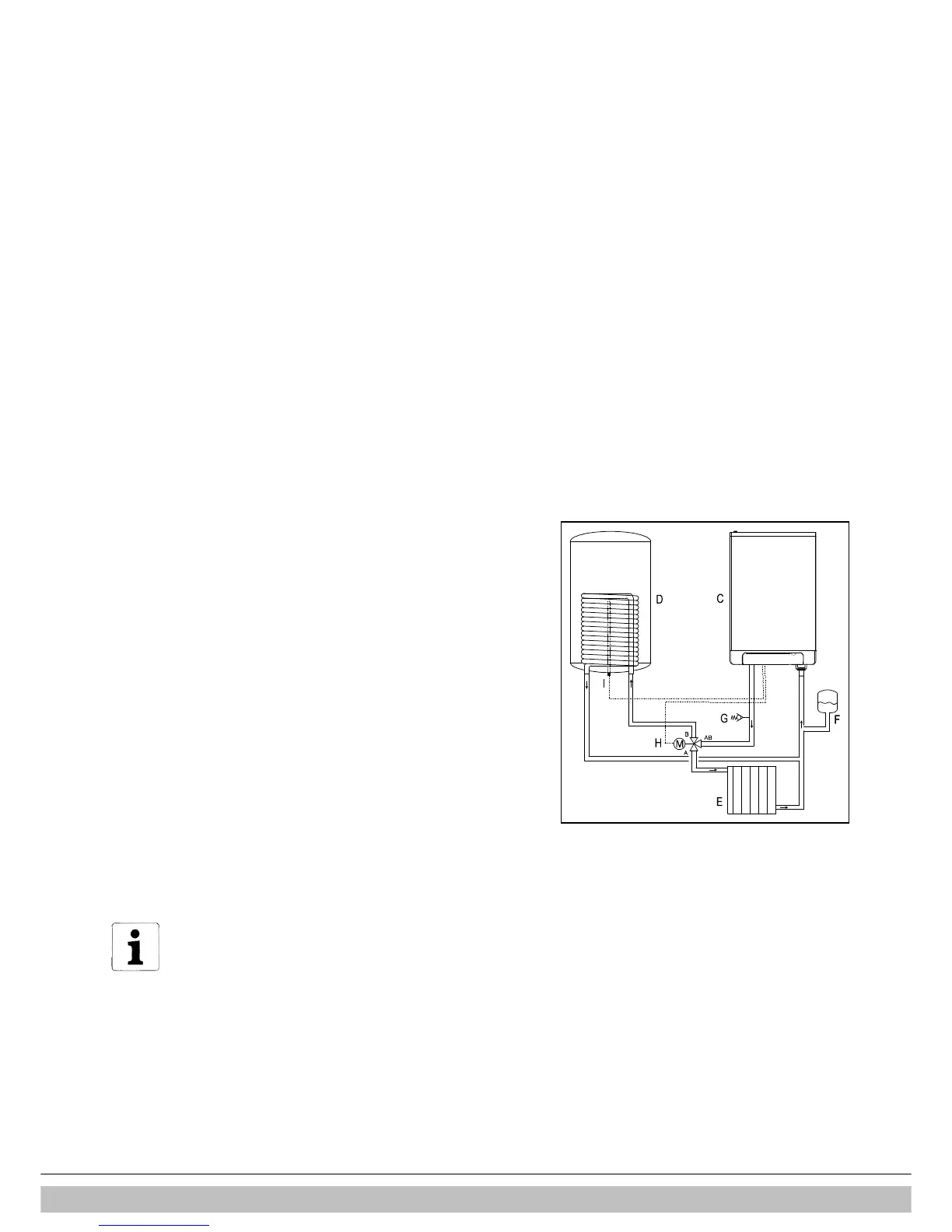
Electrical diagram indirectly heated DHW storage cylinder
C. Boiler
D. DHW storage cylinder
E. Radiator
F. Expansion vessel
G. Pressure relief valve 3 Bar
H. Diverter valve
I. DHW storage cylinder sensor or thermostat
 Loading...