Intergas Heating Ltd
35
10.4 Setting maximum CH power
The maximum CH power is set at maximum (85% ) in the factory. If less power is
necessary for the CH installation, the maximum CH power can be changed by
changing the fan rpm. See table Setting CH power.
This table shows the relationship between the fan rpm and the appliance power.
Setting CH power
Desired CH power (in kW approx.) Setting on service display (in % of
max. rpm)
18 SB
NOTE
The power during burning is increased slowly and is reduced as
soon as the set supply temperature is reached (modulate on T
flow).
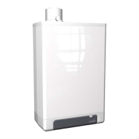
10.5 Adjusting pump setting
The switch for adjusting the pump setting is located on the CH pump connection box
(Factory setting III).
1. Adjust the pump setting depending on the maximum power set and the water
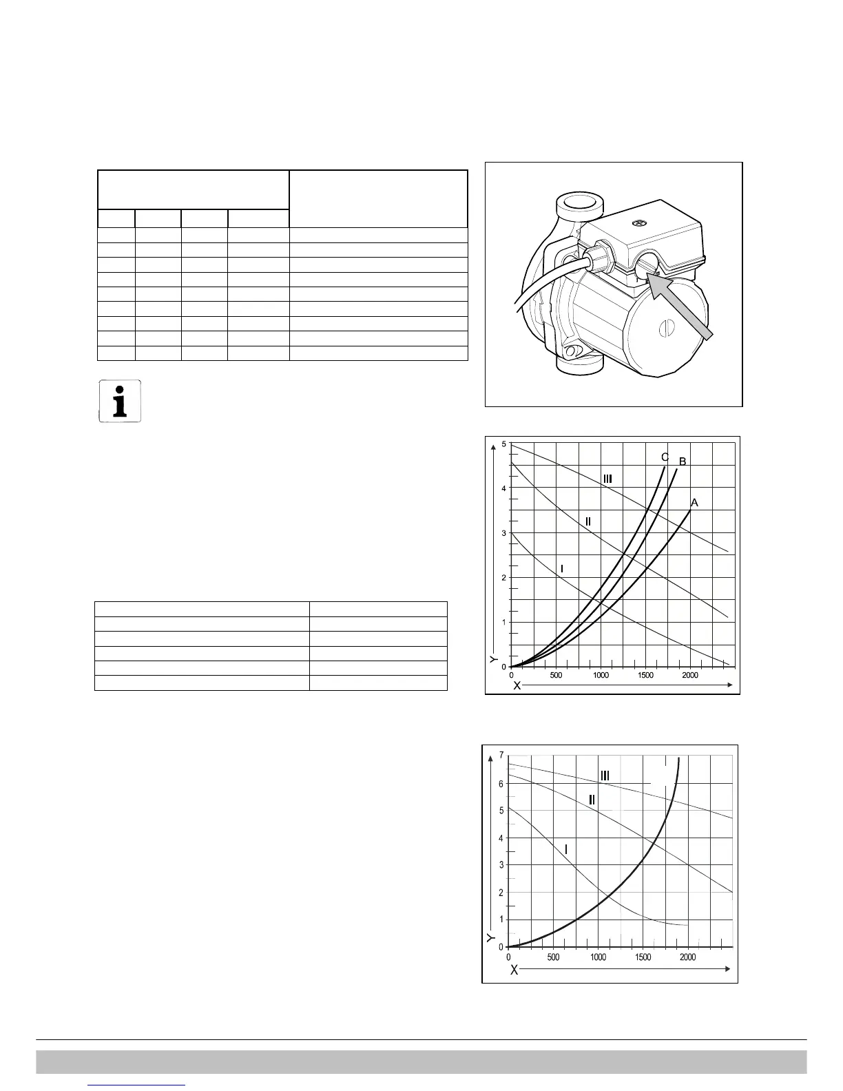
resistance of the installation. See diagram: pressure loss of appliance and
pump water head, positions I, II and III.
2. Check the temperature difference between the appliance supply and return:
this must be approximately 20°C.
The minimum flow quantity (l/h) Power setting (kW)
155 5,4
510 17,8
650 22,8
750 26,3
1150 40,9
Appliance pressure loss graph, CH side
A. Compact HRE 18 SB
B. Compact HRE 24 SB
C. Compact HRE 30 SB
AA. Compact HRE 40 SB
I Pump setting I
II Pump setting II
III Pump setting III
X Flow in l/h
Y Pressure loss / water head in mH
2
O
WILO RS 15/4.1 (SB18, 24 & 30)
WILO RS 15/7-3 (SB 40)
 Loading...