Goodrive20-EU series VFD Function parameters
78
Detailed instruction of parameters
FDT1 electrical
level detection
value
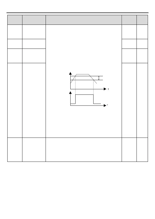
When the output frequency exceeds the
corresponding frequency of FDT electrical level,
the multi-function digital output terminals will
output the signal of "frequency level detect FDT"
until the output frequency decreases to a value
lower than (FDT electrical level—FDT retention
detection value) the corresponding frequency,
the signal is invalid. Below is the waveform
diagram:
Output frequency
FDT level
Y,
RO1, RO2
FDT lag
Setting range of P08.32: 0.00Hz – P00.03
(the max. frequency)
Setting range of P08.33 and P08.35: 0.0 –
100.0%
Setting range of P08.34: 0.00Hz – P00.03
(the max. frequency)
FDT1 retention
detection value
FDT2 electrical
level detection
value
FDT2 retention
detection value
Amplitude
value for
frequency
arrival
detection
When the output frequency is among the below
or above range of the set frequency, the
multi-function digital output terminal will output
the signal of "frequency arrival", see the diagram
below for detailed information:
 Loading...


