0A-20 General Information
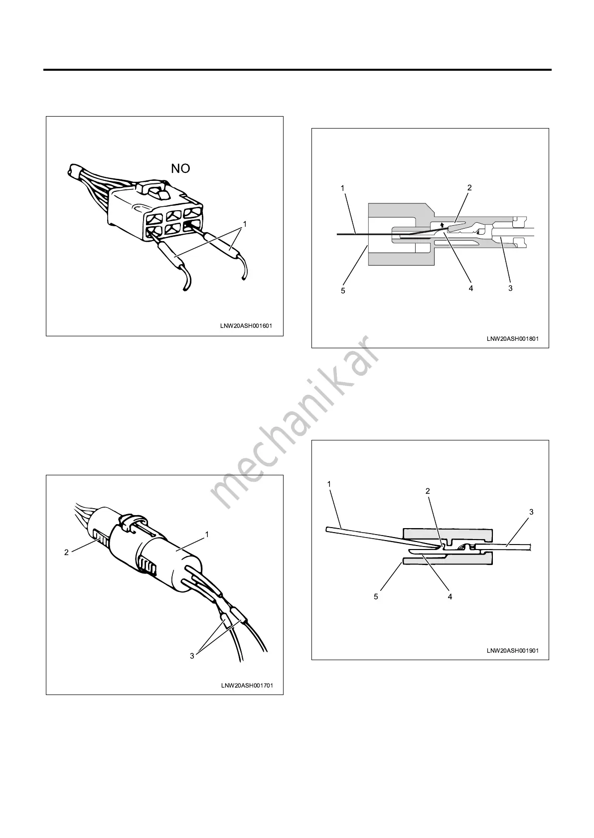
Never insert the probes (1) from the connection closure
area of the connector, as this will cause the connector
terminals to break.
Inspection requirements for waterproof connector
circuit
For waterproof connectors, the probes of the tester
cannot be inserted from the wiring side, due to the
structure of the connectors.
Therefore, perform the continuity inspection as
indicated in the diagram, by connecting a testing
connector (1) prepared in advance to the connector (2)
to test, and connect the probes (3) of the tester to the
harness of the testing connector.
Disconnecting connector terminals
—Built-in lock type
1. As indicated in the diagram, insert a thin
screwdriver-shaped metal rod (1) from the
connector closure area (5).
2. Push the lock (2) up in the direction of the arrow
using the metal rod to release the lock. In that
state, pull out the harness (3) together with the
terminal (4).
—Terminal lock type
1. Insert a metal rod (1) from the connector closure
area (5).
2. As indicated in the diagram, release the terminal
lock (2) by pushing it to the harness side, pull out
the harness (3) together with the terminal (4).
Connecting connector terminals
1. Check that the terminal lock (1) area is raised fully
and can be locked.
2. Insert the terminal (3) from the harness (2) side of
the connector, and push it in until the lock area
clicks.
NO
LNW20ASH001601
1
LNW20ASH001701
3
2
1
LNW20ASH001801
4
3
5
1
2
LNW20ASH001901
45
2
3
1
LGGEN-WE-0871_7th.book 20 ページ 2009年10月1日 木曜日 午後3時26分

 Loading...