Function and Features
Copyright © Itech Electronic Co., Ltd. 13
Chapter3 Function and Features
This chapter will describe in detail how to use the buttons to complete the
basic operation of the IT6300 series power supply. Will be divided into the
following sections:
Front panel operation introduction
Switch local/remote operations
Channel switching operation
OUT ON/OFF output setting
Timer operation
Voltage setting operation
Current setting operation
Data save/recall settings
Overvoltage operation
Keypad lock function
Overheat protection
Menu function
Rear panel terminals function
3.1 Front-panel Operation Overview
The power supply is shipped from the factory ready for front-panel
operation mode. At power-on, the power supply will automatically enter
the front-panel operation mode and the instrument can be controlled via
the front panel keys and knob.
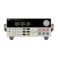
The output of power supply can be enabled/disabled from the front panel
by pressing the button. When turn on the output, the VFD will
display the state and voltage/current of each channel. ”C” represents
constant current mode. ”V” represents constant voltage mode. When
output is in OFF mode, VFD will have no any indicators of C or V.
The VFD also displays operation states or error information. “ ”means
the power supply is in remote mode. When front-panel keys are locked,
“ ” means the power supply keyboard locked .For more details, please
refer to chapter of “Descriptions about VFD marks”.
If the power supply is in set mode, you can modify parameters using the
knob. If the power supply is in menu operation, the knob is used for menu
selection.
When , , , or buttons are lit,
means they are under corresponding state now. If pressing (Shift)+
(Save), button will keeping flickering and waiting for a
number to be entered to specify the memory location.
Details about key buttons’ state:

 Loading...