Function and Features
Copyright © Itech Electronic Co., Ltd. 26
includes the following parts:
Power Model
Display the model of power supply: IT63XX
Soft Version
Firmware version of power supply: Ver: 1.XX-1.XX
Power SN
Display the serial number of the power supply: SN:XXXXXXXXXXXXXXXXXX
Calibration information
Display calibration information: 2005-8-26 17:46:13
Error Information
If error, press (Shift) + , VFD will display error information, press any
key to display the next error message, if not, then continue to display
information on above (model, the software version, serial number, etc.) Error
message will be cleared in the display, but fault still exist.
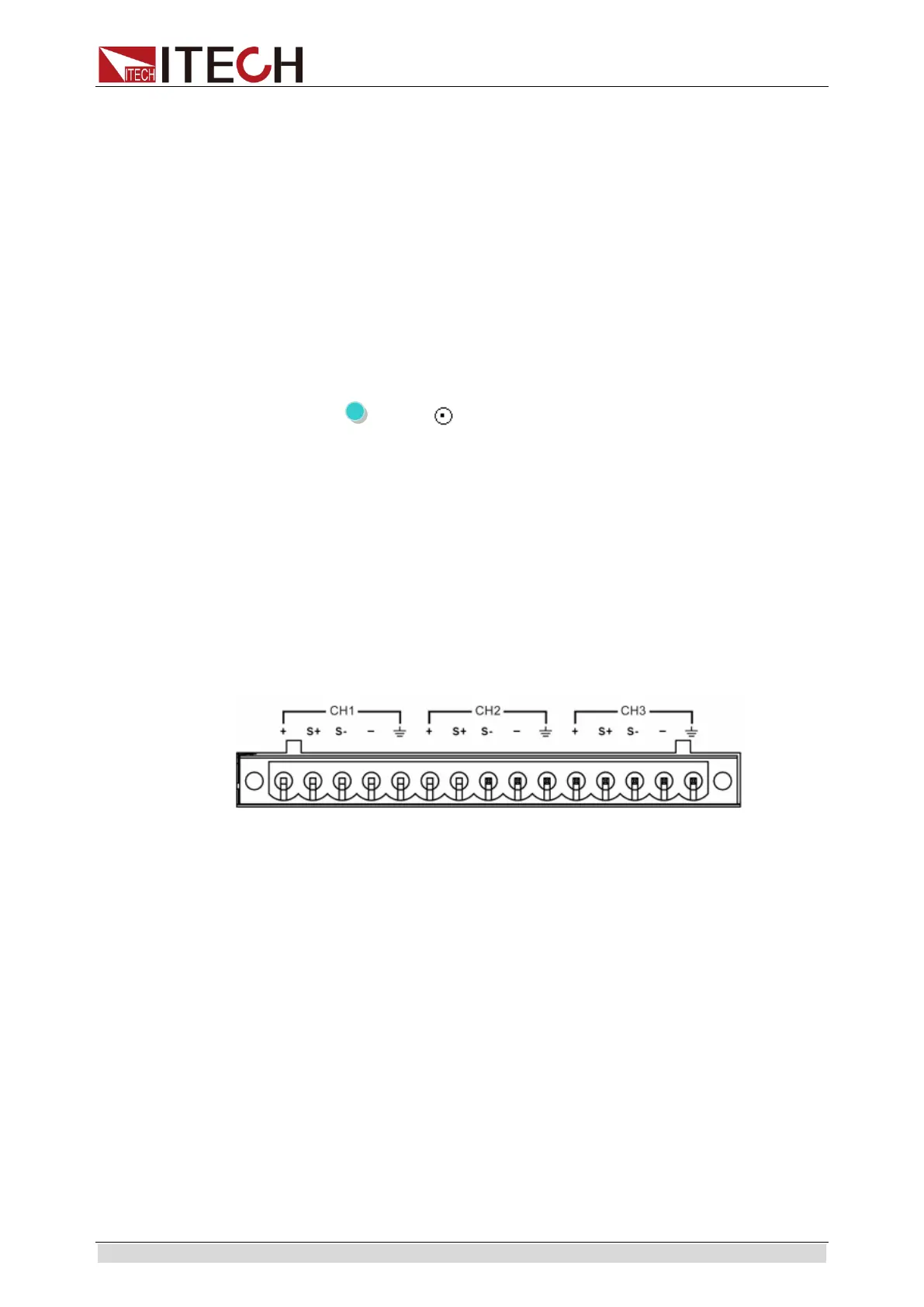
3.13 Rear Panel Terminals Function
Remote voltage sensing is used to maintain good regulation at the load and
reduce the degradation of regulation that would occur due to the voltage drop
in the leads between the power supply and the load. By connecting the supply
for remote voltage sensing, voltage is sensed at the load rather than at the
supply’s output terminals. This will allow the supply to automatically
compensate for the voltage drop in the load leads and improve regulation.
+, -: Output terminals, the same as front pane output terminals.
S+, S-: Remote sensing terminals.
Disable remote sense function:
1. Use the standard shorting clip which has been installed before leave the
factory. Or you can also use wires to short “S+” and “+”, “S-” and “-”.
2. Connect the output “+” and “-” terminals of the corresponding channel on
the front panel to the device under test.
Enable remote sense function:
1. Remove the shorting clip between “S+” and “+”, “S-” and “-”.
2. Connect “S+” and “S-” to the device under test.
3. Connect “+” and “-” to the device under test.

 Loading...