Function and Features
Copyright© Itech Electronics Co., Ltd. 59
Slave: Salve mode.
Master: Master mode. If Master mode is selected, you need to set the
number of Salves for the Master.
Mount: total number of instruments in parallel. For example, Mount=3.
4. After setting of host and slave, switch off the power supply. Connect the
networking.
5. Connect the networking as shown above. Please connect the network after
parallel setup. Otherwise, at start up, the power supply will detect parallel
setup fault and fail to start up.
When connecting the system bus, please note the built-in terminal
matching resistance at the rear panel. If the resistance is removed,
the instrument may not work properly. The user can install the
terminal matching resistance on the Input end of the first system bus
and the Output end of the last system bus.
The system bus interface is not isolated from the output electrode.
After power on, it is not allowed to insert or pull out the bus and
terminal matching resistance.
3.24 Rear Panel Terminal Functions
If the tested instrument consumes large current, a large voltage drop will be
detected in connection line between tested instrument and power supply
terminal. To ensure measurement accuracy, a remote sense measurement
terminal is provided at power supply rear panel to compensate voltage drop lost
in wire.
When the power supply is used for measuring battery charge in actual
applications, the voltage drop of the wire will lead to voltage inconsistency of
both ends and inconsistency of the cutoff voltage of power supply and the
actual voltage of battery, resulting in inaccurate measurement.
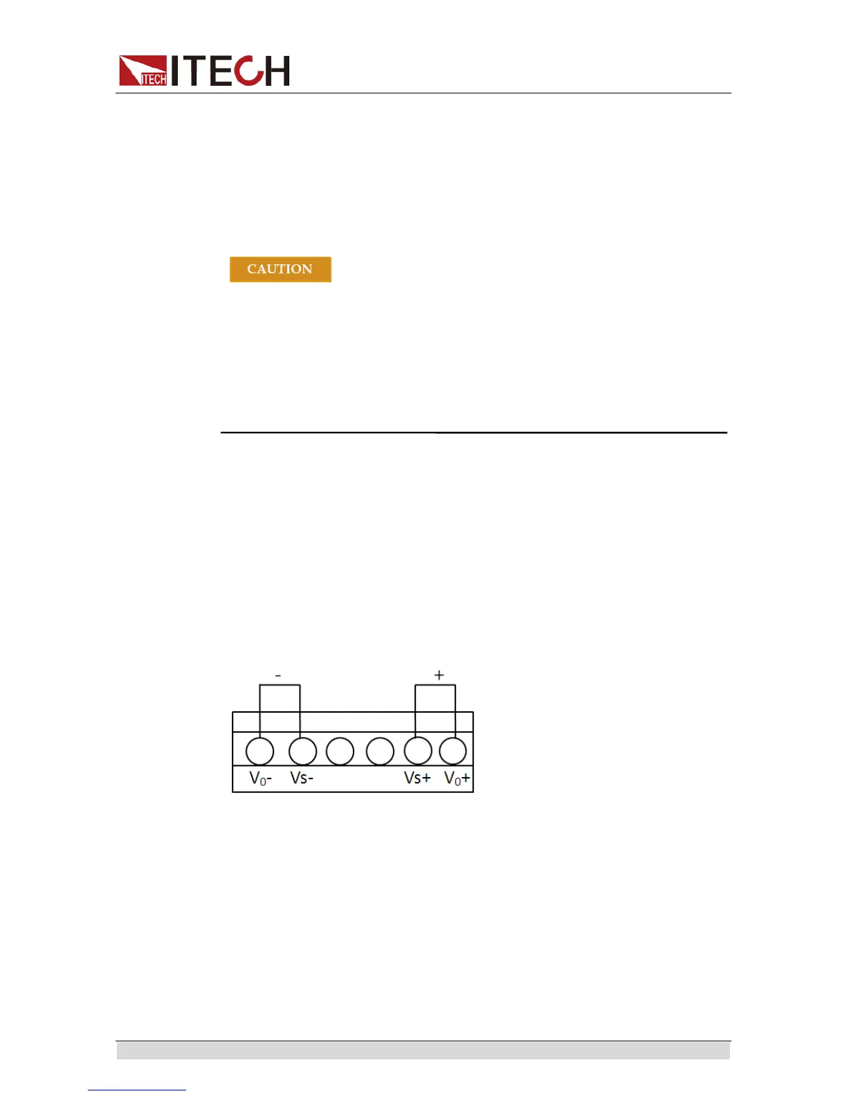
Vo+,Vo-: output terminals
Vs+,Vs-: remote sense terminal
When using the remote sense function, please cut off the connection wire
between Vo+ and Vs+, so will the line between Vo- and Vs- terminals.
Then extending lines from Vs+ to the positive terminal of undertested
product and line from Vs- to the negative terminal of undertested product.
Use local sense:
Local sense doesn’t compensate the voltage drop on the connection wire, the
operation is:
1. Connect the Vo+ and Vs+, Vo- and Vs- for short circuit using the short clips
 Loading...


