EasyManua.ls Logo

ITT Flygt 4901 User Manual

ITT Flygt 4901
101 pages
To Next Page IconTo Next Page
To Previous Page IconTo Previous Page
Page #28 background imageLoading...
Page #28 background image
28
Antes del arranque
La bola descansa sobre la membrana inferior. El aceite
permanece en la cámara de aceite, la membrana exte-
rior está elevada y la inferior descendida.
Cuando la bomba se pone en marcha
La válvula está abierta cuando la bomba se pone en
marcha. El flujo de ésta circula por la válvula y limpia el
pozo de la bomba. En el cuerpo de la válvula se produ-
ce un vacío inducido por el flujo. Dicho vacío empieza
a invertir las posiciones de las membranas superior e
inferior y eleva la bola. Ver la figura 1 abajo.
Al cabo de aprox. 20", el aceite de la cámara pasa al
espacio entre la membrana inferior y el fondo del cuer-
po de la válvula, a través de la válvula de regulación,
forzando la membrana inferior a invertirse, impulsando
así la bola hacia el chorro de líquido. Entonces la bola
obstruye el flujo por la válvula y la bomba empieza a
extraer el líquido del pozo. Ver la figura 2.
Figura 2.
Figura 3.
Figura 1.
Antes del arranque por primera vez:
Durante el período de prueba existe un cierto ries-
go de que la válvula quede obstruida por partículas
sólidas y fangos levantados del sedimento en el
fondo. Para impedir este inconveniente se reco-
mienda vaciar el pozo y limpiarlo antes de empe-
zar a usar la válvula de limpieza.
FUNCIONAMIENTO
Una vez la válvula cerrada, el vacío se convierte
instantáneamente en sobrepresión, que fuerza las
membranas y el aceite a sus posiciones iniciales.
Ver la figura 3.
Question and Answer IconNeed help?

Do you have a question about the ITT Flygt 4901 and is the answer not in the manual?

ITT Flygt 4901 Specifications

General IconGeneral
TypeControl Unit
Frequency50/60 Hz
Power Consumption10 W
Protection ClassIP 66
Housing MaterialPolycarbonate
Weight1.5 kg
Dimensions200 x 150 x 100 mm
Operating Temperature-20 to +60 °C
Storage Temperature-40 to +70 °C (-40 to +158 °F)

Summary

Installation, Care and Maintenance

PRODUCT DESCRIPTION

General

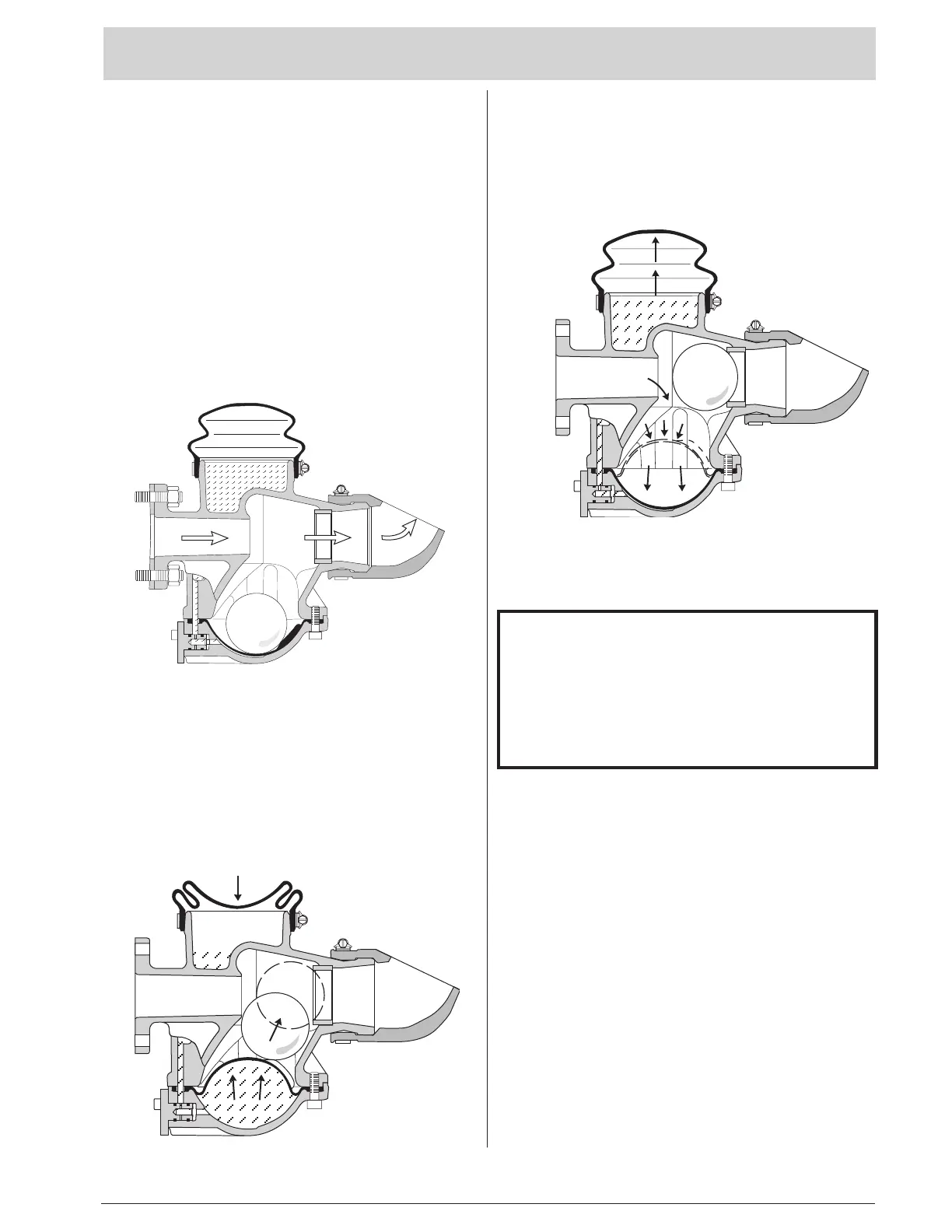
Primary function and operation of the flush valve, including its mechanism.

Applications

Specifies where the flush valve is used and the necessary installation prerequisites.

Performance

Details the flushing capacity and coverage area of the flush valve.

MATERIAL

DESIGN

INSTALLATION

Safety Precautions

Essential safety advice to be followed during the installation process.

Mounting the Flush Valve on the Pump

Step-by-step instructions for securely attaching the flush valve to the pump housing.

Setting Flushing Time

Guidance on how to adjust the duration of the flushing cycle.

Adjusting the Regulating Valve

Instructions for fine-tuning the regulating valve to control flush time.

FUNCTION

Before Start

Describes the initial state of the valve components before pump activation.

When the Pump Starts

Explains the valve's operational sequence and diaphragm movement upon pump startup.

Before First Start

Recommendations and precautions for the initial operation of the flush valve.

INSPECTION AND SERVICE

Oil

Details regarding the type of oil used and its properties in the flush valve.

Inspection

Guidelines for regular inspection of the valve and its components.

Major Overhaul

Information on the recommended schedule for significant maintenance overhauls.

TROUBLESHOOTING

PARTS LIST

Related product manuals