6
INSTALLATION
Safety precautions
See the “Care and Maintenance” for the appropriate
pump.
Mounting the flush valve on the
pump
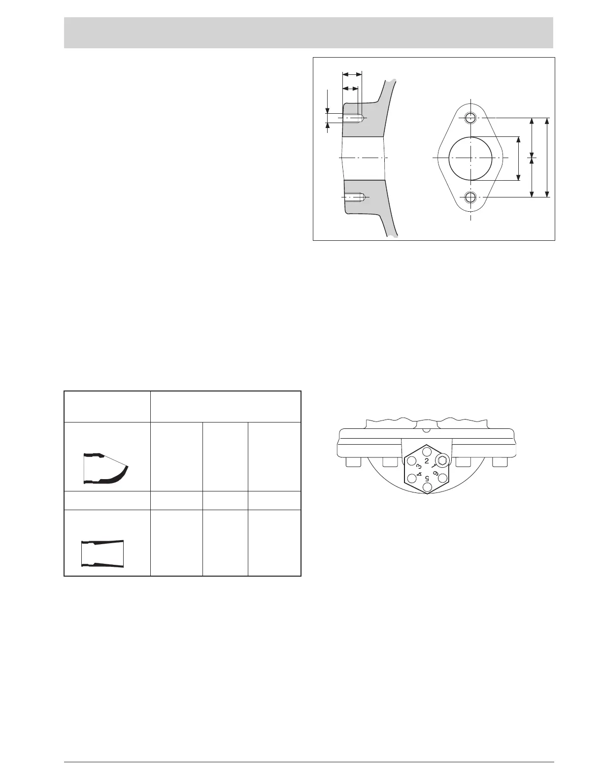
The pump housings are pre-drilled and must be
equipped with a cast flat for the flush valve connection.
The drilling pattern is shown in Figure B. For further in-
formation, contact your nearest Flygt representative.
Setting flushing time
The 4901 flush valve is designed to support the three
possible executions;
1) with outlet bend
2) with outlet pipe
3) execution
without
outlet bend and
without
outlet
pipe is called “short outlet”.
The flushing time is determined by the regulating valve.
The delivery setting is “2”.
Recommended
approximative
first setting of the
regulating valve:
Execution Geodetic Pump Head (m).
< 4 4–10 > 10
Outlet bend
586 68 00 1 2 3
Short outlet 2 3 3–4
Outlet pipe
558 08 00 2 3 4
The recommended flushing period is 20 seconds.
Note. The flushing time for the special version may
vary more than for the standard version.
“Setting 2”
For a
shorter
flushing period, turn the regulating valve
to a
lower
setting.
Lock the regulating valve with the locking screw.
Note:
The flushing period is also affected by the oil viscosity
(the temperature of the water or of the air) and of the
underpressure in the valve body. The outlet pipe gives
the best underpressure and the outlet bend gives the
poorest underpressure. Therefore – be aware of the
limits!
Note. If the flush valve 4901 is used with the APF, a
maximum flushing period of 45 seconds should not
be exceeded.
Adjusting the regulating valve
Loosen the locking screw.
For a
longer
flushing period, turn the regulating valve
to a
higher
setting.
23
18
84
42
42
M 10
ø 46
Figure B
 Loading...