EasyManuals Logo
Home>IVT>Heat Pump>C7

IVT C7 User Manual

IVT C7
100 pages
To Next Page IconTo Next Page
To Previous Page IconTo Previous Page
Page #42 background imageLoading...
Page #42 background image
Electrical connections
6 720 643 409 (2010/03)
42
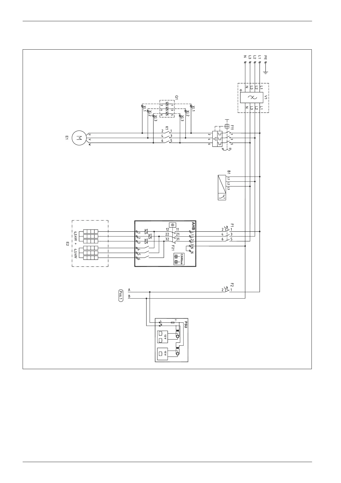
10.4.5 Internal wiring diagram E14-E17
Fig. 45 Internal wiring diagram
B1 Phase guard
E1 Compressor
E2 Electric add. heat
F1 Automatic fuse electric additional heat
F2 Miniature circuit-breaker heat pump
F11 Motor cut-out compressor
F21 Overheat protection electric additional heat
K1 Contactor compressor
Q1 Soft starter (accessory)
V1 EMC filter (accessory)
X1 Terminal block
PSU Circuit board
AHB Circuit board
6 720 641 855-28.1I

Table of Contents

Questions and Answers:

Question and Answer IconNeed help?

Do you have a question about the IVT C7 and is the answer not in the manual?

IVT C7 Specifications

General IconGeneral
BrandIVT
ModelC7
CategoryHeat Pump
LanguageEnglish

Related product manuals