64
FOR THE INSTALLER
5. Make the necessary settings on the control panel.
a. Confi rm connected external sensors. If T3 (GT3), T4 (GT4) or T5
(GT5) have been connected, you must confi rm these so the control
unit knows they are installed. The displays presented by the sensors
are only shown if the sensors have been confi rmed.
B. Set the maximal output to be used by the electric cassette. Choose
between 1/3, 2/3 and 3/3. It is important that the electrical installa-
tion is adapted to handle the maximum electrical output. On delivery
the control unit is set to 2/3. For more information about this see the
heading Technical information.
Menu displays you might need to adjust or
check
Temperature settings
Set the hysteresis for heat pump on/off switching on the return sensor T1
(GT1). A lower value gives a shorter interval between start and stop. Less
than 5ºC should be avoided.
Set the neutral zone for the mixing valve in a heating system with two heat
curves. In the neutral zone the mixing valve receives no signal to open or
close. Only applies when the sensor T4 (GT4) is connected.
Set the maximum temperature in the mixing valve circuit. You can, for
example, set a maximum temperature for the fl oor heating system. On
delivery of the heat pump the value is 60ºC. Only applies when the sensor
T4 (GT4) is connected.
Hot water settings
Set the temperature in the hot water heater’s outer shell. Note that the
setting does not apply to the temperature inside the hot water heater. The
factory setting is 51ºC, but this temperature can be increased to max 54ºC
if necessary. Only applies when the sensor T3 (GT3) is connected.
Set the hysteresis for the hot water temperature. The function measures
below and above the value set in menu 2.3. Only applies when the sensor
T3 (GT3) is connected. Less than 4ºC should be avoided.
Clock setting of additional heat
You can set the control unit so that the additional heat is fully blocked
during certain periods of the day. Read more under the heading Extra
functions (Customer level 2) / Timer control about how to set the control
unit.
Commissioning the heat pump
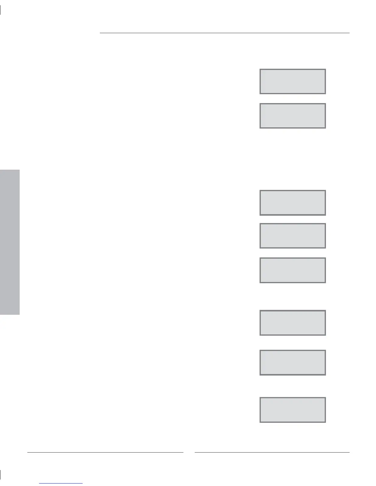
Temperature settings
Heat curve
hysteresis 1.4
Return Select
Temperature settings
Mixing valve curve
neutral zone 1.8
Return Select
Temperature settings
Mixing valve curve
max at GT4 1.9
Return Select
Hot water setting.
Setting of
temperature. 2.3
Return Select
Hot water setting.
Setting of
DHW hysteresis 2.4
Return Select
Clock setting
Clock sett. add heat
accord. to clock 4.2
Return Select
Commiss./Service
Connected extra
sensor in op 5.13
Return Select
Commiss./Service
Select conn capacity
electrical cass 5.2
Return Select
 Loading...


