J-200
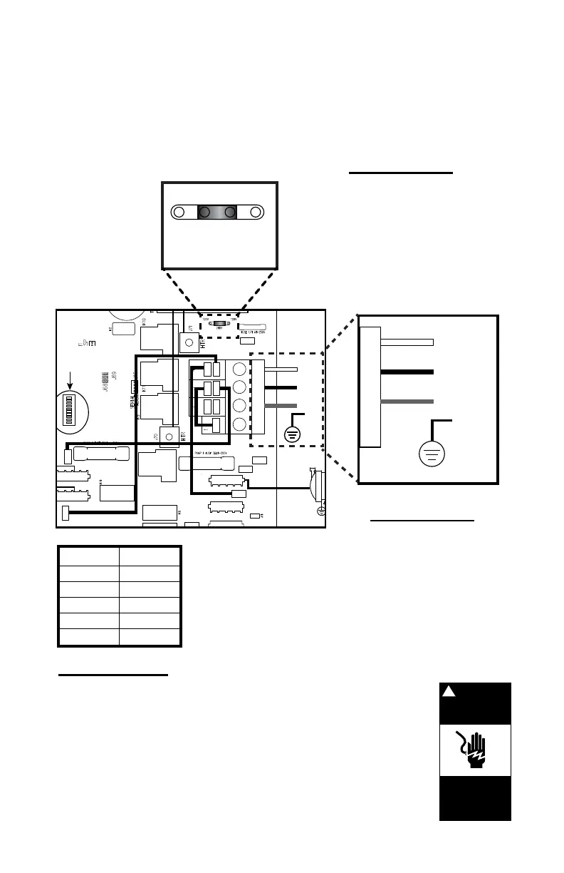
16.3 North American J-210, J-215 and J-225 Convertible Power
Models (For a 4-wire 240V 60 Hz connection)
This wiring diagram is used for all North American 240V 60 Hz
convertible power models. Dedicated 240V models must be permanently
connected (hard-wired) to the power supply.
Note: 240 VAC 4-wire connection enhances heater output from 1kW to
4kW.
DANGER
Turn power off
before servicing. This
task should only be
performed by a quali-
fied technician.
!
RISK OF SHOCK OR
ELECTROCUTION!
Location J22
remove one logic
jumper and place
the other across the
240V pins, as shown
TB1 terminal
White wire must
be connected to
location D and
a second hot
wire connected
(RED), as shown
Jumper wires
The sequence of the
jumper wires must be
changed, as shown
CIRC PUMP
L-BLK
N-WHT
G-GRN
WHT
BLK
4.0KW
G-GRN
G-GRN
See Section 17.0
for Dip Switch
Settings
240 VAC, 20A/31A
4-WIRE CONNECTION
60HZ 1-PHASE SERVICE
30A (PMP 1)
30A (PMP 2)
J33
J36
J53
J41
J46
J47
J51
J59
J38
J44
J49
J22
F4
J27
J34
J22
120V 120V
240V
A
B
C
D
WHT
BLK
RED
TB1
G-GRN
FROM TO
J37 J38
J51 J46
J59 J53
J33 J47
J22
1 jumper
1 2 3 4 5 6 7 8 9 10
55
 Loading...