Page 10
ENGLISH
Jandy
®
AquaLink
®
TCX™ Power Center
|
Installation & Operation Manual
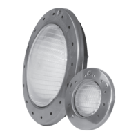
3.3.2 Low Voltage Wiring
1 2 3 4 5 6 7 8 9 10
LVH SOLAR WATER AIR SPARE
1 2 3 4 5 6 7 8 9 10
LVH SOLAR WATER AIR SPARE
Figure 5. Green 10 Pin Connector Close Up
NOTE: Permanently separate high and low voltage wiring by
using corrugated tubing.
1. Connect the low voltage RS-485 communication
wires.
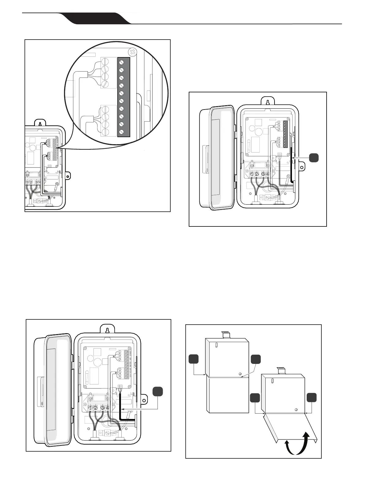
2. If JVA is present, thread JVA connector through
the lower right corner of the board, through the
side knockout and strain relief tting.
3. Connect JVA cable, see Figure 6 (a).
a
1 2 3 4 5 6 7 8 9 10
LVH SOLAR WATER AIR SPARE
Figure 6. Pool Only Version, Connect Line Inputs &
JVA Cable
4. Install Low Voltage Wires. Install the wires for
the temperature sensor connections through the
side knockout, see Figure 7 (a).
5. Connect wires in the order listed on the board.
6. Check all connection points and wiring for secure
connections.
a
1 2 3 4 5 6 7 8 9 10
LVH SOLAR WATER AIR SPARE
Figure 7. Connect Low Voltage Wires
7. If bottom half of dead panel needs to be removed
use some diagonal pliers to cut the two rear tabs,
see Figure 8 (a).
8. Cut dead panel label across dead panel opening,
see Figure 8 (b).
9. Swing dead panel bottom back and forth until
front tabs break o, see Figure 8 (c).
a
c
c
b
Figure 8. Reinstall Dead Front

 Loading...