Section 2.
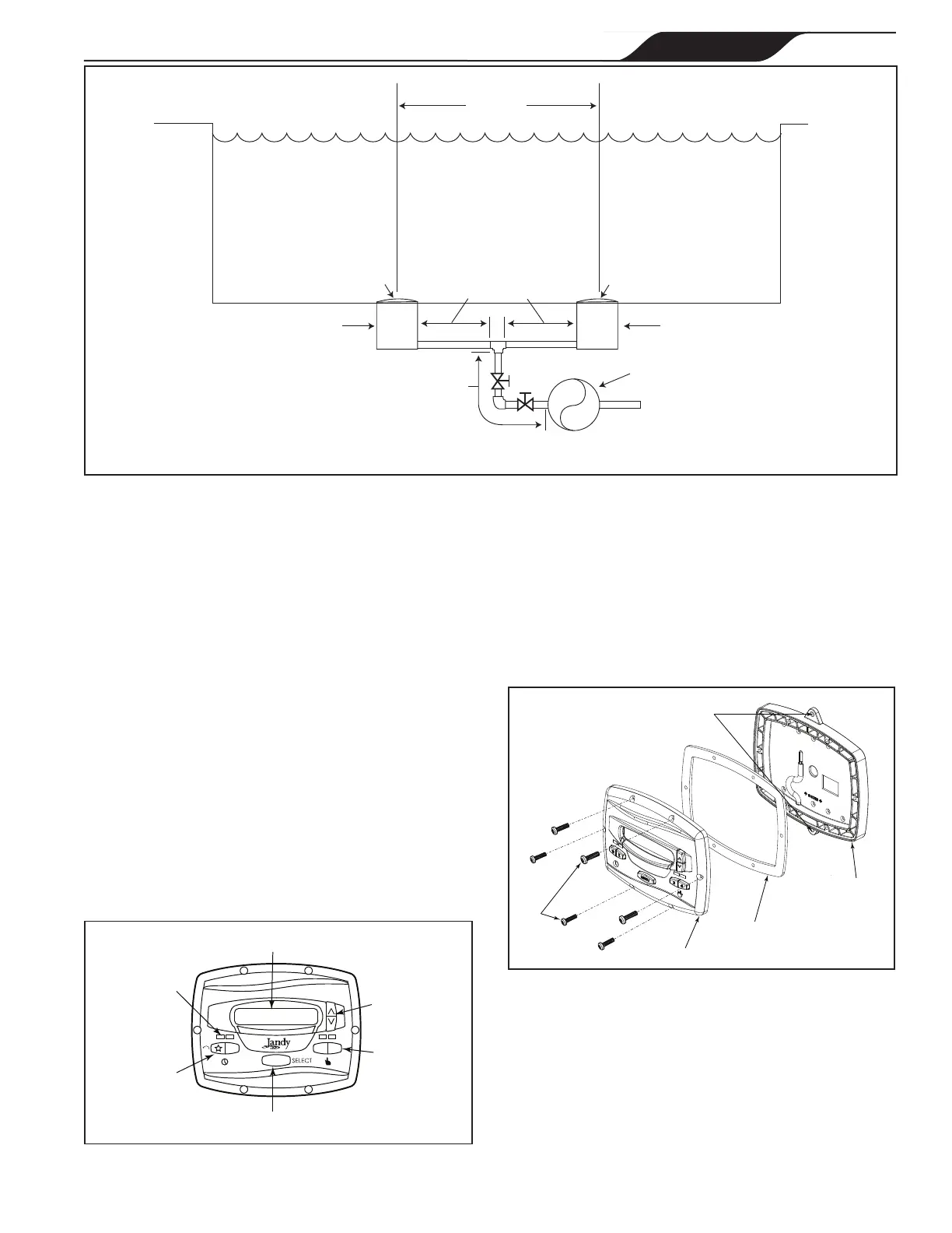
At Least
3 Feet
Suction Outlet
(Main Drain)
Suction Outlet
(Main Drain)
No Valves between
Tee and Main Drains
Listed/Certified to latest
published edition of
ANSI
®
/ASME
®
A112.19.8
or its successor standard,
ANSI/APSP-16
Anti-entrapment
Cover/Grate or Suction
Fitting, Securely-fastened
to Main Drain Sump
Listed/Certified to latest
published edition of
ANSI
®
/ASME
®
A112.19.8
or its successor standard,
ANSI/APSP-16
Anti-entrapment
Cover/Grate or Suction
Fitting, Securely-fastened
to Main Drain Sump
Valves OK between
Pump and Tee
WARNING: Suction check valves and hydrostatic valves should not be used with this pump.
Pump
Figure 1. Number of Suction Outlets Per Pump
Installation of the
Digital Controller
2.1 Introduction
This document provides general instructions to
install and operate the JEP-R Variable-Speed Digital
Controller. The controller can be mounted to an
electrical gang box (single, double, or triple) or to a at
wall.
The instructions have been written with safety as the
priority, and must be followed exactly. Read through the
instructions completely before starting the procedure.
2.2 The Controller Panel
The controller panel provides both timed and manual
speed controls for the Variable Speed Pumps.
Four (4) speeds are directly available on the panel,
while four (4) additional speeds may be accessed via the
MENU key.
LCD Display
Preset Speed
Buttons
Menu Button
LED Lights
Up/Down
Arrow Keys
2
3
4
PRESS SPEED OR MENU
12:00AM PUMP IS OFF
MENU
eStar Button
Figure 2. JEP-R Controller Panel
The up and down keys are used to adjust the pump
speed. The speed is saved as it is adjusted. No further
action is required to save the new speed setting after
adjustment. The selected speed can be saved and
assigned to one of the speed buttons.
As shown in Figure 2, preset speed "
" is assigned to
the "eStar" feature. Hence, it is intended to be assigned
an energy-ef cient ltration speed, as determined by the
installer.
External Brackets
For Wall Mounting
Figure 3. Controller Components
2.3 The Controller Components
The controller assembly contains the following
components. See "Figure 3. Controller Components":
1. Controller
2. Mounting Gasket
3. Backplate
4. Six (6) Screws
PAGE 7
ENGLISH
JEP-R Variable-Speed Pump Controller
|
Installation Manual
 Loading...