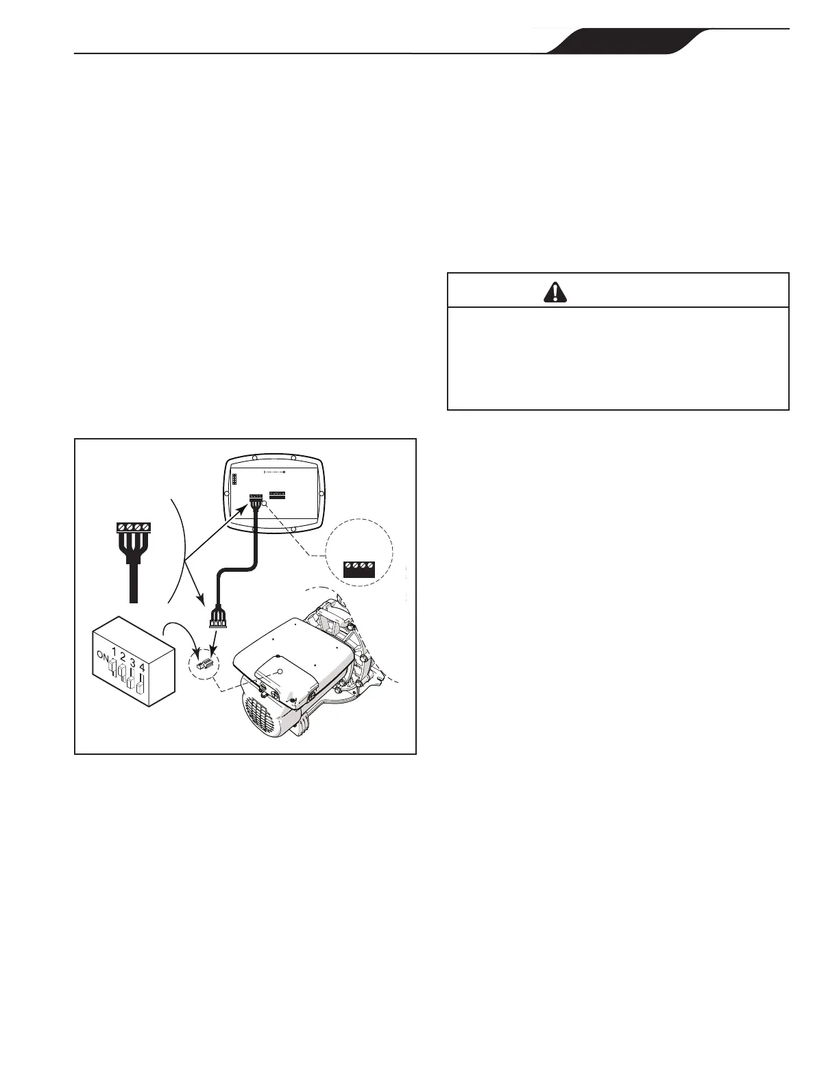
NOTE The controller uses a four-wire RS-485 interface
to communicate with the ePump.
5. Unplug the RS-485 connector from the pump.
6. Attach the four (4) wires in the RS-485 cable
to the RS-485 connector. Make sure the colors
match the positions on the connector. See "Figure
4. Wiring the Controller to the Variable Speed
Pump"
7. Connect the RS-485 connector back into the
pump.
8. Set the DIP switch settings for the pump controller
with the 1 and 2 in the ON position and 3 and 4
in the OFF position. See "Figure 4. Wiring the
Controller to the Variable Speed Pump".
9. Turn on all switches and the main breaker feeding
power to the pump.
10. Verify the operation of the controller. If
the controller displays
FAULT PUMP NOT
CONNECTED, re-check the wiring and the DIP
switch address setting on the pump.
BLACK
YELLOW
RED
GREEN
RS485
4321
RED
BLACK
YELLOW
GREEN
REMOTE CONTROL
54321
INPUT 2
INPUT 3
INPUT 4
COMMON
INPUT 1
4-Position
DIP Switch
Variable-Speed
Pump Motor
Controller
(Rear View)
RS485
Cable
4321
BLACK
YELLOW
RED
GREEN
Figure 4. Wiring the Controller to the Variable Speed
Pump
2.7 Variable Speed Pump Switch Settings
For the ePump™, the VS-FHP2.0 pump and the
VSPHP27, the 4-position or 5-position dip switch is
located at the rear of the pump, as shown in "Figure 4.
Wiring the Controller to the Variable Speed Pump"
This dip switch serves two functions, it determines what
type of control will be used with the pump and it selects
the pump address. The SW 1 (switch 1) and SW 2 are
turned ON if the pump is to be controlled by a JEP-R
controller or OFF if the pump is to be controlled by the
AquaLink
®
RS, AquaLink PDA or AquaLink Z4. See
"Table 1. DIP Switch Settings".
2.8 Connection to Remote Contacts
The controller allows speeds "
" through "4" to
operate via remote contact closures (switch or relay).
Speed "4" operates differently than the other three. See
"2.10 Remote Closure 4 Behavior".
1. Turn off all switches and the main breaker that
supplies power to the variable-speed pump.
WARNING
ELECTRICAL SHOCK HAZARD
Turn off all switches and the main breaker in
the ePump electrical circuit before starting the
procedure. Failure to comply may cause a shock
hazard resulting in severe personal injury or death.
2. Connect one side of the remote contact closure
to the COMMON terminal on J3 REMOTE
CONTROL connector of the controller. See
"Figure 5. Connect to Remote Contacts"
PAGE 9
JEP-R Variable-Speed Pump Controller
|
Installation Manual
ENGLISH
 Loading...