Home
Janome
Sewing Machine
JR3203N-BC
Janome JR3203N-BC User Manual
5
of 1
of 1 rating
134 pages
Give review
Manual
Specs
To Next Page
To Next Page
To Previous Page
To Previous Page
Loading...
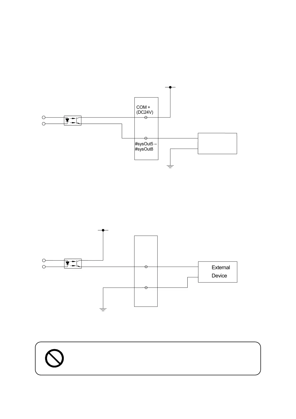
Specifications
Deskt
op Robo
t J
R
3
000
COM
-
(GND
)
Inte
rnal P
owe
r Supp
ly
DC
24V
#sysOut
5
–
#sysOut
8
Ex
t
e
r
n
a
l
De
v
i
c
e
+
-
10.10
Out
put S
ign
al (
PN
P
)
Whe
n
us
in
g
an
e
xternal
p
ower
s
uppl
y
Whe
n
us
in
g
t
he
i
nternal
p
ower
s
uppl
y
(optiona
l)
A
ssigning
th
e wron
g
wi
rin
g
to the
I
/
O
can damage
the inte
rnal
circ
uits
.
Extern
al Power
Supply DC
24V
#s
y
s
O
ut
5
–
#s
y
s
O
ut
8
CO
M
+
(D
C
2
4
V
)
+
-
Extern
al
Devic
e
71
71
73
Table of Contents
Default Chapter
2
Preface
2
Table of Contents
4
Contents
4
For Your Safety
7
1 Lineup
16
Understanding the Model Number
18
2 Identification Plate
19
Reading the Identification Plate (Sample)
19
Identification Plate Locations
20
3 I/O Polarity
22
4 External Dimensions
25
Unit External Dimensions
25
Jr3203
25
Jr3204
27
Jr3303
29
Jr3304
31
JR3403 Single Column (Standard)
33
JR3403 Double Column (Optional)
35
JR3404 Single Column (Standard)
37
JR3404 Double Column (Optional)
39
Unit Fixtures (4 Locations)
41
Common to the JR3200 Series
41
Common to the JR3300 Series
42
Common to the JR3400 Series
43
Teaching Pendant (Optional)
44
Switchbox
45
5 Range of Movement
46
6 Attaching Equipment
47
7 I/O-Sys
49
Connectors
49
Pin Nos. (Robot Side)
51
Cable Wiring
51
Output Capacity
52
Input Signal (NPN)
53
Output Signal (NPN)
54
Circuit Diagram (NPN)
55
Input Signal (PNP)
57
Output Signal (PNP)
58
Circuit Diagram (PNP)
59
8 I/O-Sys Function Assignment
61
9 Fieldbus Function Assignment
62
10 I/O-1 (Optional)
63
Connector
63
Pin Nos. (Robot Side)
65
Function Assignment List
65
Cable Connection
66
Power Supply Capacity
66
Input Signal (NPN)
67
Output Signal (NPN)
68
Circuit Diagram (NPN)
69
Input Signal (PNP)
71
Output Signal (PNP)
72
Circuit Diagram (PNP)
73
11 I/O-S (Optional)
75
Connector
75
Pin Nos. (Robot Side)
76
Safety Device
77
12 Fieldbus (Optional)
78
Fieldbus Settings
79
Devicenet
80
Connector Diagram
80
Network Status
80
Module Status
80
Connector Pin Assignment
80
Settable Contents
81
Profibus
81
Connector Diagram
81
Operation Mode (OP) / Status (ST)
82
Connector Pin Assignment
82
Settable Contents
82
Profibus Master (PLC) Settings
83
CC-Link
84
Connector Diagram
84
Run (RUN) / Error (ERR)
84
Connector Pin Assignment
84
Settable Contents
84
13 I/O-Mt (Optional)
87
Connector
87
Pin No. (Robot Side)
88
Function Assignment
88
Cable Wiring
89
Output Capacity
90
Input Signals
90
Output Signals
91
Circuit Diagram
92
14 Memory Port
93
Teaching Data Backup
94
System Software and PS Data (Model Setting Data) Updates
95
MEMORY Port Settings (Administration Settings Mode)
96
15 Lan Port
97
Connector
97
Pin Nos. (Robot Side)
98
16 Com 1 - 3
99
Connector
99
Pin Nos. (Robot Side)
100
COM Connector Pin Connection
100
17 Tpu (Teaching Pendant Connector)
102
Connector
102
Pin Nos. (Robot Side)
103
Pin Connections
103
Circuit Diagram
104
18 Switchbox Connector (Switchbox Specifications)
105
Connector
105
Pin Nos. (Robot Side)
105
Circuit Diagram
106
19 Command List
107
Point Job Data
107
Execute Conditions
111
PLC Programs
111
20 Variable List
112
21 Function List
115
22 System Flag List
119
23 Error Message List
121
5
Based on 1 rating
Ask a question
Give review
Questions and Answers:
Need help?
Do you have a question about the Janome JR3203N-BC and is the answer not in the manual?
Ask a question
Janome JR3203N-BC Specifications
General
Brand
Janome
Model
JR3203N-BC
Category
Sewing Machine
Language
English
Related product manuals
Janome JR3203N-AC
134 pages
Janome JR3303N-AC
134 pages
Janome JR3303N-AJ
134 pages
Janome JR3403N-AC
134 pages
Janome JR3403N-BC
134 pages
Janome JR3300 series
128 pages
Janome JR3400 series
128 pages
Janome JR1012
2 pages
Janome JW8100
60 pages
Janome JF 1004
58 pages
Janome JEM GOLD 660
23 pages
Janome JemPlatinum 760 JP760
46 pages
 Loading...