12
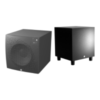
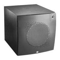
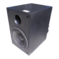
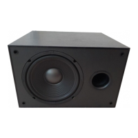
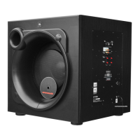
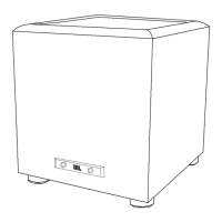
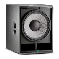
Amplifier/Subwoofer PSW-D112/DPS-12
PSW-D112/DPS-12 TESTING PROCEDURE (REV0 ONLY)
A. Power Amp Section
1. Resistance Check
Resistance from O/P of the module to GND should be >1M (NO LOAD)
Resistance from V+ of the module to V- of the module should read >5k
Resistance from V+ of the module to O/P of the module should read >1M
Resistance from V- of the module to O/P of the module should read >1M
2. Power Up LED RED
- With a 35mV signal to Low level input, LED should change to GREEN
3. D.C. Operation
-Voltage measurements (DVM)
Between +6V V+ O/P V- +15V S/D FR I/P GND -15V
And V- GND GND GND GND V- GND GND GND GND
Should
be
Reading
+6.2V +90.1V 0V -90.1V +15.5V +5.75V 0V 0V 0V
-15.5V
4. Check Switching Frequency
-Use scope (EITHER USES AN ISOLATION TRANSFORMER OR ATTACHES THE
PROBE TIP TO SPK- and REFERENCE LEAD TO SPK+)
-Reading 100kHz +/-10%,500mVpp
B. Pre Amp Section
1. Low Level Input Sensitivity
-Set up Turn level and Low-Pass Pot Fully CW
Generator set at 100mV@39Hz
Signal to Low level input
-Voltage measurements
OP AMP
U1(14) U1(7) U1(1) U2(8) U2(14) U2(1) U4(1) U4(7)
SPEAKER
OUTPUT
271mV 409mV 486mV 471mV 456mV 460mV 2.94V 2.67V 17.4V
2. High Level Input Sensitivity
-Set up Turn level and Lo Pass Pot Fully CW
Set Generator at 3.6V@39Hz
Signal to High level input
-Voltage measurements 17.4V at speaker output
 Loading...