33
VTX A8 | User Manual
13 - TESTING VTX A8
Speakers need to be periodically checked and maintained in order to assure long-term performance and reliability, and the VTX A8 is
no exception. While the system is designed for utmost reliability, it is important to confirm that the system is operating within specified
tolerances to ensure optimal performance for years to come. Below are two methods that can be used to check and verify proper trans-
ducer performance in a VTX A8 system.
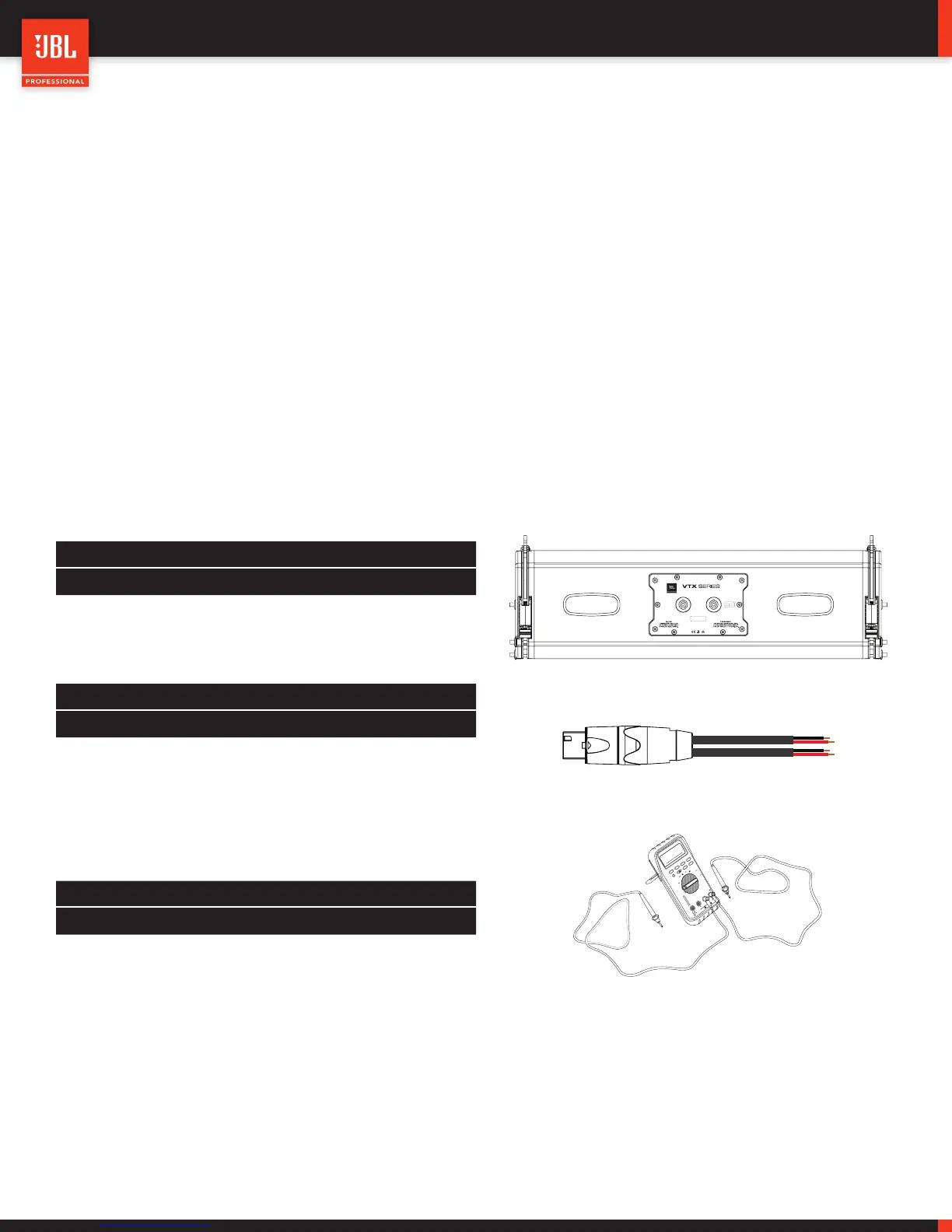
13.1 - USING A DMM (DIGITAL MULTI METER)
This method is best suited for when the speaker system is in the shop. A DCR (DC resistance) test with a multimeter can give a very
accurate reading of how many transducers are properly wired together and within their standard operating tolerances. This test is ap-
propriate for individual boxes and not groups.
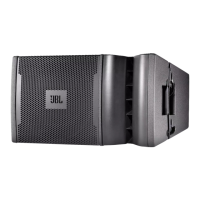
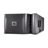
With the A8 speaker unplugged from any amplifiers, set a DMM to the resistance (Ω) setting and place the probes across the Pin1+/-
and Pin 2+/- leads. Record the values indicated on the DMM for each pair of leads and refer to the chart below to either confirm correct
readings or investigate out-of-tolerance DCR readings. Note that a passive network is used between the MF and HF sections, any major
deviations from the values listed belows should be further examined by removing the input panel and testing the individual components.
A8 MF/HF Section (Pin 2)
DCR Tolerance
All drivers functioning 6.5 Ω +/- 0.2 Ω
Any driver shorted 0.2 Ω -
A8 LF Section (Pin 1)
DCR Tolerance
All woofers functioning 5.2 Ω +/- 0.2 Ω
1 x woofer open 10.1 Ω +/- 0.2 Ω
2 x woofer open OL -
Any driver shorted 0.2 Ω -
Notes:
• The DCR numbers listed above assume cold (room temperature) transducers. If taken right after use, and when the transducers are
warm, the numbers will vary. For best results test the speakers cold.
• The DCR value of a transducer gives an accurate representation of its electrical state. Any mechanical defects are not characterized
by this test. Refer to the VTX A8 service manual for instructions on how to perform a rub-and-buzz test using a sine wave generator.
B18
DCR Tolerance
B18 functioning 4.5 Ω +/- 0.2 Ω
Driver shorted 0.2 Ω -
Designed in Los Angeles, CA
Made in Mexico
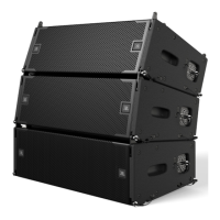
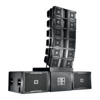
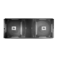
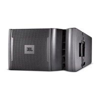
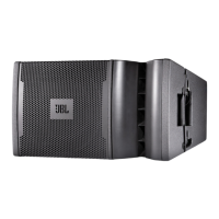
A8
Compact Dual 8” Line Array Element
PINOUT
Pin 1
Pin 2
LF
MHF
IN/OUT IN/OUT
 Loading...