34
VTX A8 | User Manual
Pins Section DCR Tolerance
Pins 1 & 2 LF Right 10.1 Ω +/- 0.2 Ω
Pins 7 & 8 LF Left 10.1 Ω +/- 0.2 Ω
Pins 3 & 4 MF Right 12 Ω +/- 0.2 Ω
Pins 9 & 10 MF Left 12 Ω +/- 0.2 Ω
Pins 5 & 11 HF 1 20 Ω +/- 0.2 Ω
Pins 6 & 12 HF 2 20 Ω +/- 0.2 Ω
1 2
3 4 5 6
7 8
9 10 11 12
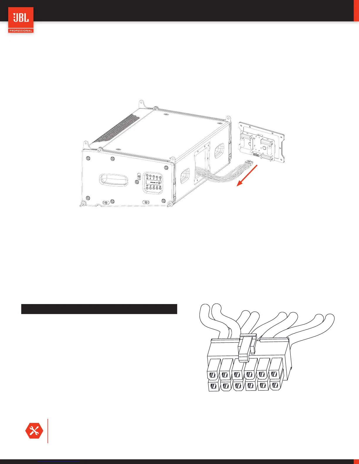
13.1 - TESTING INDIVIDUAL COMPONENTS
Testing the individual sections of an A8 enclosure requires removing the input panel and bypassing the passive network. To do that first
remove the 10 x T15 screws holding the panel, and then slide the input panel out of the A8 enclosure. Once the panel has been removed,
disconnected the Molex
TM
connector from the board as illustrated below.
The Molex
TM
connector includes 12 connection pins which can be used to test the individual sections of the A8 speaker using a DMM.
The pin assignments of the Molex
TM
connector are listed below and note that the locking tab of the connector should be oriented facing
up. The test leads of a DMM can be inserted in the connector pins to take the measurements. The DCR values of each section should
be within tolerance of the values listed below. Since each pair of MF transducers are wired in series, if an open (overload) is measured,
one or both of the transducers might be defective.
TOOLS REQUIRED: A TORX size 15 screwdriver is required to remove the screws holding the input panel onto the A8
enclosure. A high-quality Digital Multi Meter is required for measuring the transducers.
 Loading...