18z-1, 19c-1, 19c-1 EP
18
19
Please see operator manual for full details.
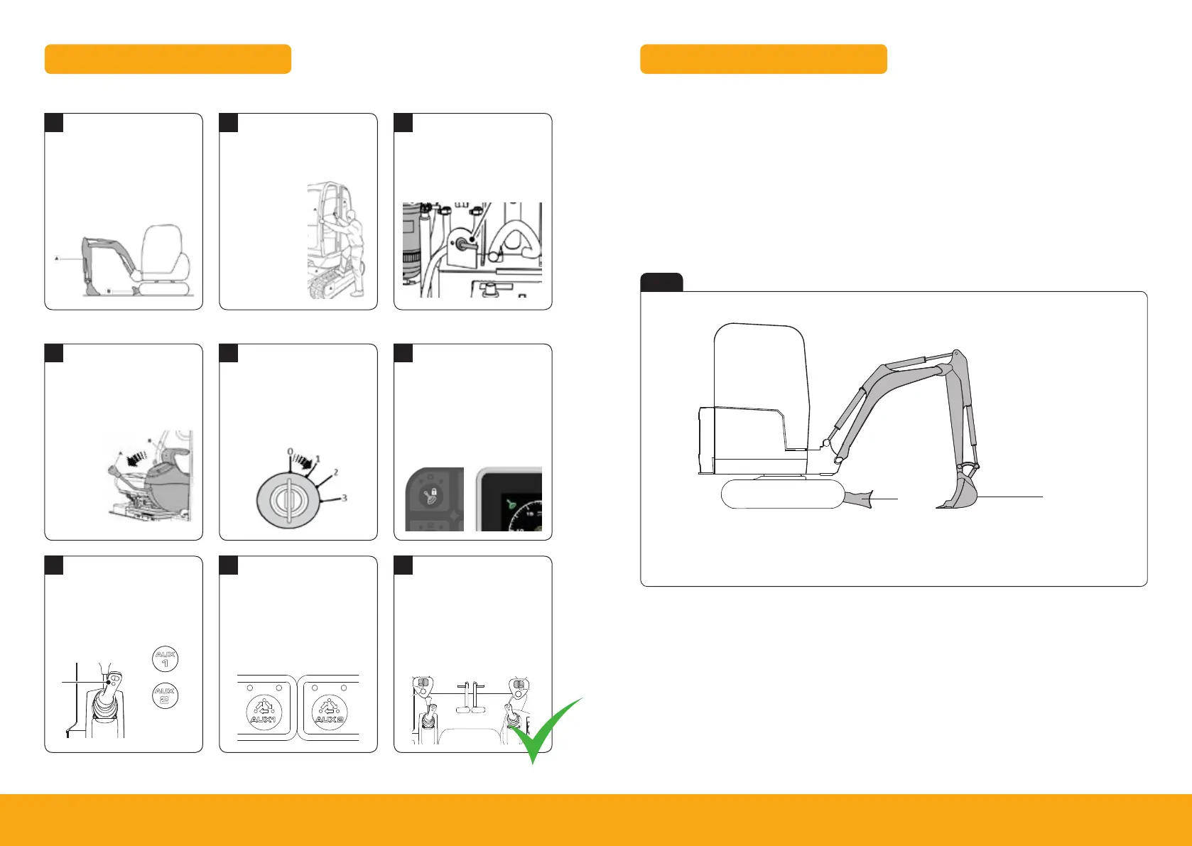
1. Park the machine on solid, level ground
I. Release the two track levers
II. Set the hand throttle lever to the idle position
2. Lower the dozer blade (A)
3. Lower the excavator so the attachment is flat on the ground
4. Stop the engine
5. Discharge the hydraulic pressure (see aux venting operation)
6. Isolate the controls and remove ignition key
7. Isolate the battery to prevent accidental operation of the engine
Maintenance Position
Fig 23
A Attachment flat on the ground
B Dozer blade lowered to ground
A
B
Maintenance
Maintenance Positions
146 9831/2900-1 146
Maintenance Positions
General
WARNING A machine can sink into soft ground. Never work under a machine on soft ground.
WARNING Make the machine safe before getting beneath it. Make sure that any attachments on the
machine are correctly attached. Engage the park brake, remove the ignition key, disconnect the battery.
Make the machine safe before you start a maintenance procedure.
Unless a maintenance procedure instructs you differently, you must lower the excavator arm. Refer to:
Maintenance Positions.
The machine has a cab tilt feature. This feature must only be used out by trained personnel. Refer to the service
manual for the cab tilt procedure.
Maintenance Position (Excavator Arm Lowered)
1. Park the machine on solid, level ground.
1.1. Release the two track levers.
1.2. Push the hand throttle lever to the idle position.
2. Lower the dozer. Refer to Figure 111.
3. Lower the excavator so the attachment is flat on the ground. Refer to Figure 111.
Figure 111.
4. Stop the engine.
5. Discharge the hydraulic pressure.
Refer to: Discharge.
6. Isolate the controls.
Refer to: Control Lock.
7. Disconnect the battery to prevent accidental operation of the engine.
Shutdown and Auxiliary Venting
Shutdown Sequence
1
1
4
2
2
5
3
3
6
Park Machine Up
Lower LH Arm Rest
Select Aux Circuit
Leave & Secure
Turn Ignition On
Switching Circuits
Isolate Machine
Press 2 GO Button
Venting Aux Circuit
Park machine on solid level
ground with the attachment (A)
and dozer (B) on the ground.
While sitting in the operating
station with engine off lower
LH arm rest.
Enable aux function on top of
the left control lever (A). Ensure
symbol (B) or (C) is displayed.
Turn ignition to position 1 (A) so
that the instrument panel and
switches become active.
Change Aux mode between
Aux1 (A) and Aux 2 (B) using
mode select switch on the right
hand console.
Press 2 GO button (A) to
activate hydraulics. Instrument
panel will illuminate (B)
when active.
Operate the roller switch fully
in both directions to release
stored pressure. Right hand
(A) for Aux 1 and left hand (B)
for Aux.
Switch off all switches. Leave
machine using the handrails
and footholds.
Close & lock
all doors and
windows to
secure machine.
Turn isolator key anti-clockwise
and remove key.
A
Auxiliary Venting (Within 1 Minute of Shutdown)*
A Handle
B LH arm rest
A
A
B
A B
About the Product
Console Switches
26 9831/2900-1 26
(For: 19C-1)
Figure 19.
G
H
I
J
K
A
B
C
D
E
F
0 1
2 3
4 5
6
7
8 9
Table 7.
A Control isolation solenoid on/
off switch
LED (Light Emitting Diode) illumination: Hydraulics active
B Aux 1 (high flow) selection
switch
Mode: Single acting, Double acting system 1 or 2. No LED illumina-
tion.
C Lift overload switch LED illumination: Buzzer silenced
D Worklights on/off switch LED illumination: 1= Front on, 2= Rear on
E Wiper/washer on Push to change wiper function (Intermittent /on/off). Hold to operate
washer. LED Illumination: 1= Intermittent wiper, 2= On wiper, 1 & 2 =
Washer active
F Auto-hydraulic warming switch Not used.
G H+ mode selection switch Not used.
Operation
Operating Levers/Pedals
83 9831/2900-1 83
The electro-proportional switch on the right joystick controls swing or high flow attachments (press the change
over button on the left joystick to select auxiliary mode). An icon is displayed on the instrument panel. The
finger button on the right joystick can be used for hammer (constant full flow).
The electro-proportional switch on the left joystick controls low flow attachments.
Figure 67. 19C-1
E
A
B
D
C
A Tilt/grab changeover for tilt-rotator B Boom swing/aux changeover
C Left electro-proportional switch for aux 2 (low
flow)
D Right finger button - hammer
E Right electro-proportional switch for aux 1 (high
flow) or boom swing
A
B
C
*19c-1 EP only please refer to the operators manual for 19c-1 and 18z-1
Operation
Instruments
72 9831/2900-1 72
Figure 52.
A
B
A Fuel level gauge B Warning and indicator lamps
Fuel level: The needle position shows the fuel level.
Warning and Indicator Lamps
Figure 53.
Table 9.
A Master warning Audible/Visual. If amber light illuminate then contact JCB dealer. If red light
illuminate then stop the machine immediately and contact your JCB dealer.
B Quickhitch unlock Illuminate amber when quickhitch is unlocked.
Operation
Operating Levers/Pedals
83 9831/2900-1 83
The electro-proportional switch on the right joystick controls swing or high flow attachments (press the change
over button on the left joystick to select auxiliary mode). An icon is displayed on the instrument panel. The
finger button on the right joystick can be used for hammer (constant full flow).
The electro-proportional switch on the left joystick controls low flow attachments.
Figure 67. 19C-1
A Tilt/grab changeover for tilt-rotator B Boom swing/aux changeover
C Left electro-proportional switch for aux 2 (low
flow)
D Right finger button - hammer
E Right electro-proportional switch for aux 1 (high
flow) or boom swing
B
A
 Loading...