16
JCB-MS-254SB-L
Instruction & User Manual
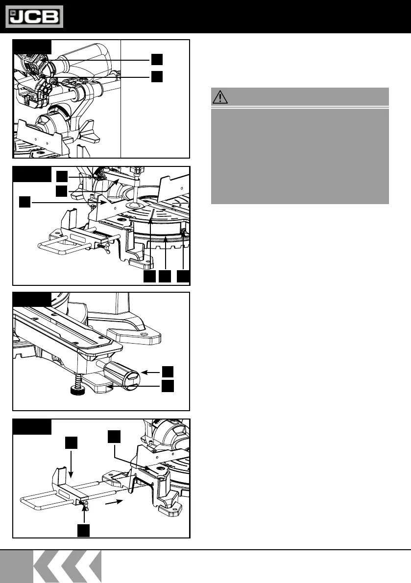
Assembling the saw (Fig1/2/3/4)
• In order to adjust the turn table (14) loosen
the locking handle (11) approx. 2 turns and
lift up the release lever (28).
• Turn the turn table (14) and pointer (12) to
the desired angle measurement on the scale
(13) and secure with the locking handle (11).
• Pressing the machine head (4) lightly
downwards and removing the fastening bolt
(23) from the motor bracket at the same
time disengages the saw from the lowest
position.
• Swing the machine head (4) up.
• It is possible to secure the clamping device
(7) to the left or right on the fixed saw table
(15). Insert the clamping device (7) in the
hole on the rear side of the stop rail (16) and
secure it with the star grip screw (7a).
• Attach the workpiece supports (8) to the
fixed saw table (15) as shown in Figure 4 and
fasten with the screw (9).
• It is possible to tilt the machine head (4) a
max. 45° to the left by loosening the locking
screw (22).
For your own safety, only insert the mains plug
in an outlet when all assembly steps have been
completed and you have read and understood
the safety and operating instructions.
Lift the saw out of the packaging and place it on
your work bench. (Positioning of the saw on
the work bench - see the previous page under
“Before starting the equipment”)
WARNING!
ASSEMBLY AND
OPERATION
Fig.1
Fig.2
Fig.3
Fig.4
11
28
8
9
15
4
26
16
7a
7
121314
 Loading...