18
JCB-MS-254SB-L
Instruction & User Manual
• Move the machine head (4) to its upper
position.
• Use the handle (1) to push back the machine
head (4) and fix it in this position if required
(dependent on the cutting width).
• Retract the fastening bolt (23) to release the
machine head (4).
• Place the piece of wood to be cut at the stop
rail (16) and on the turn table (14).
• Lock the material with the clamping device
(7) on the fixed saw table (15) to prevent
the material from moving during the cutting
operation.
• Move the Lock - off lever (3) to the left and
press the ON/OFF switch (2) to start the
motor.
With the drag guide (21) fixed in place:
• use the handle (1) to move the machine
head (4) steadily and with light pressure
downwards until the saw blade (6) has
completely cut through the work piece.
With the drag guide (21) not fixed in place:
• pull the machine head (4) all the way to
the front. Lower the handle (1) to the
very bottom by applying steady and light
downward pressure. Now push the machine
head (4) slowly and steadily to the very back
until the saw blade (6) has completely cut
through the work piece.
• When the cutting operation is completed,
move the machine head (4) back to its upper
(home) position and release the ON/ OFF
button (2).
ATTENTION! The machine executes an
upward stroke automatically due to the return
spring, i.e. do not release the handle (1) after
completing the cut; instead allow the machine
head to move upwards slowly whilst applying
light counter pressure.
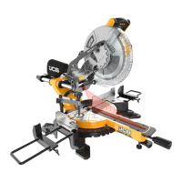
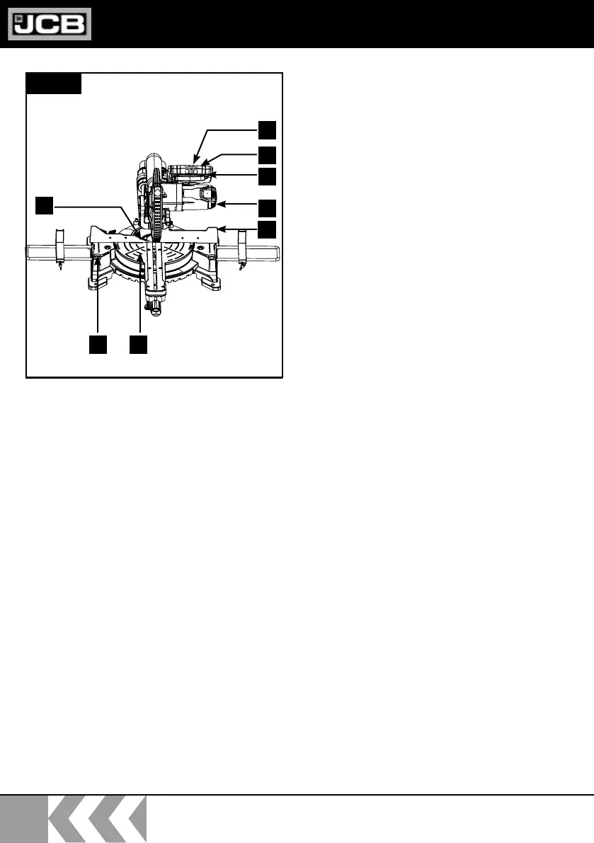
Cross cut 90° and turn table 0° (Fig.7.1
)
In the case of cutting widths up to approx.
4” (100mm) it is possible to fix the traction
function of the saw with the locking screw (20)
in the rear position. In this position the machine
can be operated in cross cutting mode. If the
cutting width is over 4” (100 mm) then it is
necessary to ensure that the locking screw (20)
is loose and the machine head (4) can move.
• Open the set screw (16b) on the moveable
extension block (16a) and push the extension
block (16a) inwards.
• The moveable extension block (16a) must
be locked in a position far enough from the
inner position that the distance between the
extension block (16a) and the saw blade (6)
is no more than 0.3” (8 mm).
• Before making the cut, check that no collision
could occur between the extension block
(16a) and the saw blade (6).
• Tighten the set screw (16b) again.
Fig.7.1
7
1415
1
3
2
16a
16b
4
16
 Loading...