4 - 13
Travel Motor Relief Pressure
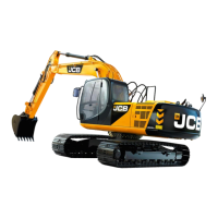
1 Prepare the Machine.
a Put the operator levers into neutral and lower the
gate lock lever. Start the engine and park the
machine on level ground. Operate the dipper out
and lower the boom to set the bucket on the
ground. Stop the engine. Release the hydraulic oil
tank pressure. (See Releasing Tank Pressure).
b Connect a 0 - 400 bar (0 - 6000 lb/in
2
) pressure
gauge and adaptor to port G1 and G2 on the
hydraulic pump (see view A on page 4 - 1).
2 If not already done, temporarily increase the pressure
setting of the MRV (see Auxiliary Relief Valves,
General, step 2).
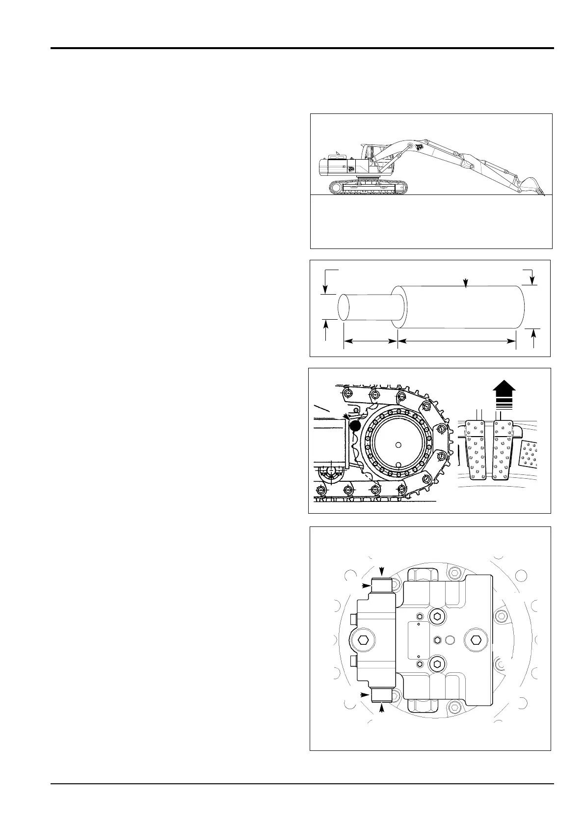
3 Insert a Lock Pin P between the drive sprocket to be
measured and the side frame.
4 Start the engine, lower the gate lock lever and run the
engine at maximum no-load speed in the S mode.
5 Slowly engage the locked travel motor and measure the
pressure in forward and reverse.
6 Pressure Adjustment
Note: For accurate setting, the pressure should be adjusted
up to the required level. Release lock nut A. Adjust setting
screw B to indicate a pressure below the required level and
then bring the pressure back up for final setting. Tighten lock
nut A.
a The pressure gauge reading (Travel motor) should
be compared to the technical data at the start of the
section. If it is outside the limits, adjust relief valve
pressure.
7 If further ARV tests are necessary carry out the relevant
procedures detailed in this section. If no further ARV
tests are required, restore the MRV pressure setting to
its original value (see Auxiliary Relief Valve, General,
step 3).
6 Stop the engine and release the hydraulic pressure (see
Releasing Tank Pressure). Remove the pressure gauge
and adaptor.
Section E Hydraulics
9803/6410
Section E
4 - 13
Issue 1
Pressure Testing
JS 03511a
JS 03230a
ø35
300
150
ø80
PP
PP
BB
AA
BB
AA

 Loading...