Lighting and Horn
Voltage Wattage No. off
Working light Tank 24 V 70 W 1
Boom 24 V 70 W 1
Roof light Cab 24 V 10 W 1
Horn 24 V 2
2 - 1
Circuit Protection;
Fuse rating and circuit names
Fuse Replacement
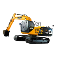
See illustration on the right for location of Fuse Box (A).
1. Prepare the machine, stop the engine remove the
starter key.
2. Prepare an appropriate fuse of the correct amperage,
remove cover.
Note: The fuse cover’s right corner is the grip.
3. Replace the blown fuse with a new one.
4. Install the fuse cover.
Note: If the reason for the blown fuse is unknown or the fuse
fails repeatedly, check the electrical circuit(s) concerned.
Section C
Electrics
9803/6400
Section C
2 -1
Issue 3*
Technical Data
BACK UP COMPUTER P.
10A 15A
KEY SW. COMPUTER C.
10A 10A
AIRCON., HEATER SHUT DOWN
20A 15A
LAMP LEVER LOCK
15A 10A
LAMP (SPARE) LUBRICATOR
15A 10A
LAMP (SPARE) WARNING BEACON
15A 10A
LAMP (SPARE) OIL PUMP
15A 20A
WIPER, WASHER CONDENSER MOTOR
15A 15A
HORN, ROOM LAMP SPARE
10A 10A
RADIO, LIGHTER SPARE
10A 10A
(A)
1
2
3
4
5
6
7
8
9
0
!
@
£
$
%
FUSEBOX
CONN 1
FUSEBOX
CONN 2
FUSEBOX
CONN 3
FUSEBOX
CONN 4
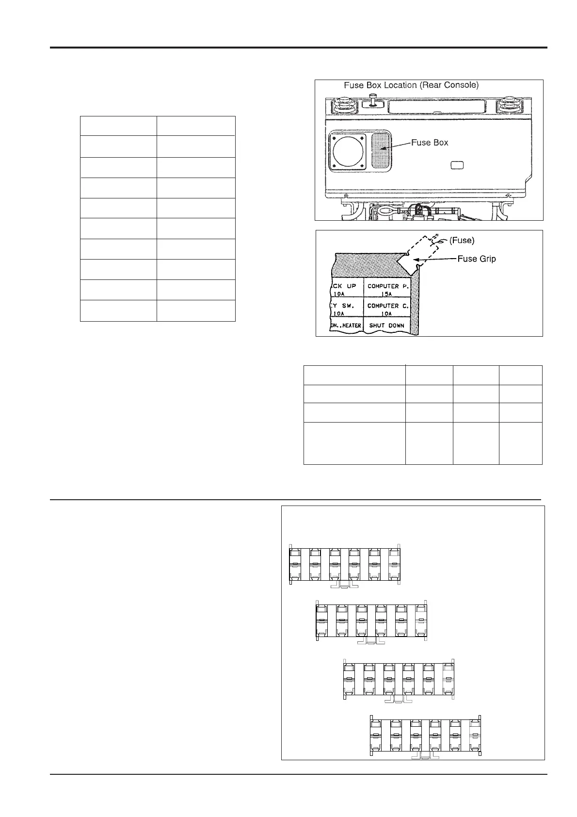
1 Radio/Lighter 10A
2 Warning Beacon 10A
3 Fuel Pump 20A
4 Lamp Option 15A
5 Lamp Standard 15A
6 Horn/ Room Light 10A
7 Back-Up 10A
8 Key Switch 10A
9 Shut Down 15A
10 Computer Power 15A
11 Computer Control 10A
12 Lever Lock 10A
13 Heater 20A
14 Wiper/washer 10A
15 Auxiliary 10A
Fuses for later Machines
The electrical circuits are protected by fuses. The fuses
are located in a fuse box on the rear console. If a fuse
blows, find out why and rectify the fault. Ensure the power
is turned off.
Fuse layout for later machines

 Loading...