21 - 1
Section E
Hydraulics
9803/6400
Section E
21 - 1
Issue 2*
Regulator JS200. JS240
Operation
Refer to the sectional drawings at the beginning of this section.
The regulator consists of the following control mechanisms:
1. Horsepower control.
Automatically reduces the pump swash angle (delivery flow) according to the increase in P
1 pump delivery pressure and P2
pump delivery pressure and limits the input torque to below a preset value.
The system operates by the summation of load pressure of the two pumps so that engine overload is prevented.
2. Power shift control (Power modes H, S, L).
The pump output horsepower set value is shifted by changing the electric current supplied to the proportional pressure
reducing valve attached to the regulator.
There is one proportional pressure reducing valve but the secondary pressure Pf (power shift pressure) goes through the
pump’s inner passages to the horsepower control part of the regulator for each pump, shifting each pump to the same
horsepower set value. With this mechanism, it is possible to change the output power of the pump to the most suitable
power for the machine application.
3. Flow rate control (Negative control).
The pump swash angle and therefore the delivery flow rate is controlled by changing the pilot pressure Pi. (see illustration D
on page 20 - 3). The regulator has the flow rate control (negative control) system in which the delivery flow rate Q reduces in
relation to valve block negative pressure. The pump delivers only the required flow so that power is not wasted.
4. Q max cut control.
Maximum delivery flow is controlled by pilot pressure Pm. This control is a two-position control so by switching ON-OFF pilot
pressure P
m, the maximum delivery flow rate can be reduced by 35%. Either of the two steps only can be selected, not
intermediate sections.
The regulator possesses the above four control mechanisms but when each control works in combination with another, the low
swash (low flow rate) instructions have priority as explained below.
Priority Mechanism of Low Tilt (Low Flow Rate) Command
As explained above, the flow rate control and horsepower control tilt commands are relayed to the feedback lever and spool
through the large hole (C, F parts) of lever 1 and lever 2. Because the C, F parts are structured so that the pin (o4) protrudes in
the large hole (o8), the lever which decreases the tilt and pin (897) touch while the o8 hole of the lever which is in the larger tilt
command state and the pin (897) do not touch and is free. By this mechanical selection method, the commands for low tilt side
for flow rate control and horsepower control have priority.
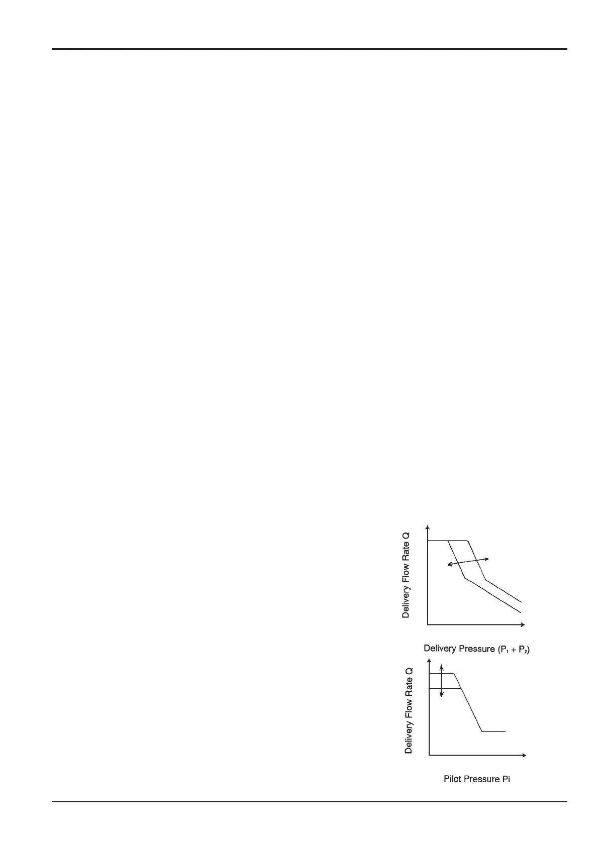
Power Shift Control
As shown in the graph, the pump horsepower is controlled at will by power shift
pressure Pf.
When power shift pressure Pf increases, the compensatory rod (623) moves to the
right through the pin (898) and compensatory rod (621) so the pump tilting angle
decreases and horsepower set is lowered, which is the same as in the explanation
for overload prevention operation of the horsepower control. On the other hand,
when power shift pressure Pf decreases, horsepower increases.
Qmax Cut Control
As shown in the graph, the maximum flow can be switched in two steps by the pilot
pressure Pm.
When pilot pressure Pm is applied, Pm pressure is led to the left of piston QMC
(648) and piston QMC overcomes the spring force of spring (646) moving the
stopper (647) and pilot piston (643) to the right and decreasing the pump delivery
flow rate.
The adjust screw QMC (642) has a collar, so piston QMC comes into contact with
that collar and stops. Thus the position of the pilot piston sets the pump maximum
flow rate.
*
*
*
*
*
*
*
*
*
*
*
*

 Loading...