23 Sailplane Section
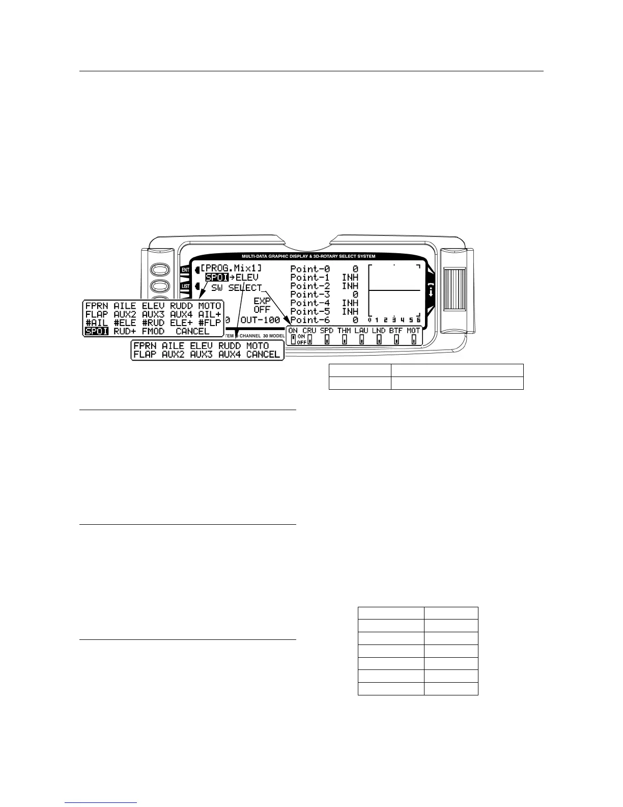
Master Channel - (Multi-Point Mixer)
This is the Master channel that receives input from the
pilot. The Master channel is selected by highlighting
and selecting this parameter to obtain a list of channels
and then selecting the Master channel from the list.
There are 4 channels that appear more than once.
They are Flap, Aileron, Elevator and Rudder. Since
these channels can be influenced by Dual Rate,
Exponential, and Throttle Curve settings, they are
included in the list twice - once where the D/R and EXP
settings are in effect and again where the D/R and EXP
settings are ignored. The second time they are listed,
there is a special designator to indicate that these
channels can also be used as a Master while bypassing
any Dual Rate and Exponential settings that may be
associated with them. They are designated by a “#”
(hash) in front of the name - #FLP, #AIL, #ELE, and
#RUD. When one of these channels is selected as the
Master, all D/R, EXP and Curve settings associated
with the Master are ignored during the mixing operation.
Instead, the mixer reads only the physical position of
the stick to perform mixing.
A (+) behind the channel indicates a trim include
function. By selecting a channel with the (+) the trim
lever effects both the master and slave channels.
BTF Mix (Butterfly) switch
MOT Gear (Motor) switch
Slave Channel - (Multi-Point Mixer)
This is the Slave channel that will move according to
the program mix in relation to the Master channel.
The Slave channel is selected by highlighting and
selecting this parameter to obtain a list of channels and
then selecting the Slave channel from the list. The list
contains each of the 9 channels in the system.
Point Names/Numbers - (Multi-Point
Mixer)
The points that can be adjusted are listed vertically by
name and are also displayed by number along the
bottom of the graph.
Change the value of a point by highlighting and
selecting the point name and dialing-in the desired
percentage.
Current Point Setting - (Multi-Point
Mixer)
This list shows the setting for each of the 7 adjustable
points (Point-0, 1, 2, 3, 4, 5, 6). The value of each point
determines where the point is positioned vertically on
the graph, which dictates the Slave servo position. The
point values can be set from -100 to +100 with -100
being full deflection in one direction and +100 being full
deflection in the other direction. A value of 0 indicates
the Slave’s center or neutral position. The overall travel
of the slave channel is determined by the Travel
settings described earlier in the TRVL ADJ. function.
A point value of INH can also be set for points 1, 2, 4,
and 5. When set to INH the point takes on a value
represented by the intersection of the cursor and the
Curve/Line between the 2 adjacent points. For instance,
if Point-1 is set to -67, Point-2 is set to INH and Point-3
is set to 0, then Point-2, which is inhibited, takes on a
value of -34, which is midway between points 1 and 3.
The value for a point can be changed by highlighting
and selecting the Point Name to the left of the point
value and then dialing-in the desired value.
Pressing the CLR button when a point value is
highlighted resets the point to original settings. The
original settings are:
Point-0 -100
Point-1 INH
Point-2 INH
Point-3 0
Point-4 INH
Point-5 INH
Point-6 +100
 Loading...