KE2000 Installation Manual
14
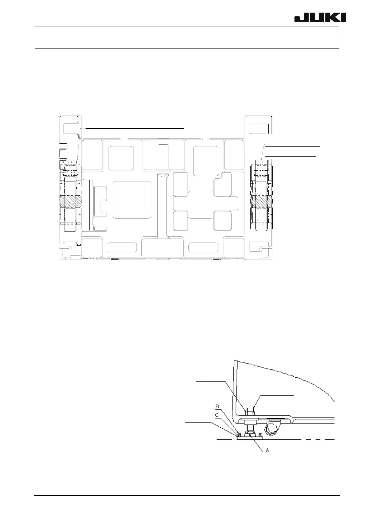
3. Adjust the adjusters (1), (3), (4), and (6) to level the machine in the back and forth, and
horizontal directions(see the fig 4-2-2). At this time, a level vial is placed on the
hatching on the top of the base frame(see the fig 4-2-3). (A level vial is placed on the
transport base unit only for EXTRA machines.)
4. Place the adjusters (2) and (5) on the floor and level the machine so that the scale on
the level vial shows the set value stated in the setting table ±1. The tra-nsport height
is adjusted to 900 mm for domestic models and 950 mm for overseas models.
5. Lock the adjust nuts. Level the machine so that the scale on the level vial shows the
set value stated in the setting table ±1.
6. Tighten three bolts A fixing the adjust bolt and adjust foot of each adjuster.
<CAUTION>
If the unit may move due to the
vibration during operation, attach the
M8 X 30 hexagonal hole bolts B (3)
and the M8 nuts C (3) packed with the
unit. Tighten the bolt B by hand. After
the tip of the bolt touches the floor,
turn it clockwise by 15 degrees with a
wrench, then fix it by the nut C. In
closing, make sure that the unit is
level. It is not recommended to place
a rubber sheet on the floor.
Fi
4-2-3
Fig 4-2-4
Viewed from the top
Transport base unit(EXTRA)
Transport base
unit(EXTRA)
d
ust foot
d
ust nuts
Hexa
on socket head bolt

 Loading...


