KE2000 Installation Manual
34
13. Interface with external equipment
13-1. KE-2020/2040
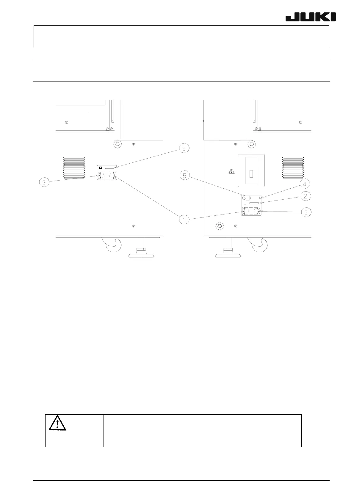
1) ① is the READY OUT (IN) connector (14-pin) to be connected to other equipment
when operating the machine main unit in the on-line mode.
The pin assignments may vary depending on the board transport direction, left to
right and right to left, and are shown in Table 13-1-1 and Table 13-1-2.
2) ② is the signal connector (50-pin) for an optional matrix tray changer.
3) ③ is the power connector (10-pin) (100V AC) for an optional matrix tray changer.
4) ④ is the printer connector (D-sub 25-pin) in conformity with the Centronics standard.
5) ⑤ is Ethernet connection port for HLC.
WARNING
WARNINGWARNING
WARNING
To prevent the body from injury which can be caused by
accidental activation of the machine , cut off the power to
the machine before starting to work.
Fig 13-1-1.
Left side view of the main unit
Fig 13-1-2.Right
side view of the main unit

 Loading...


