-
89
-
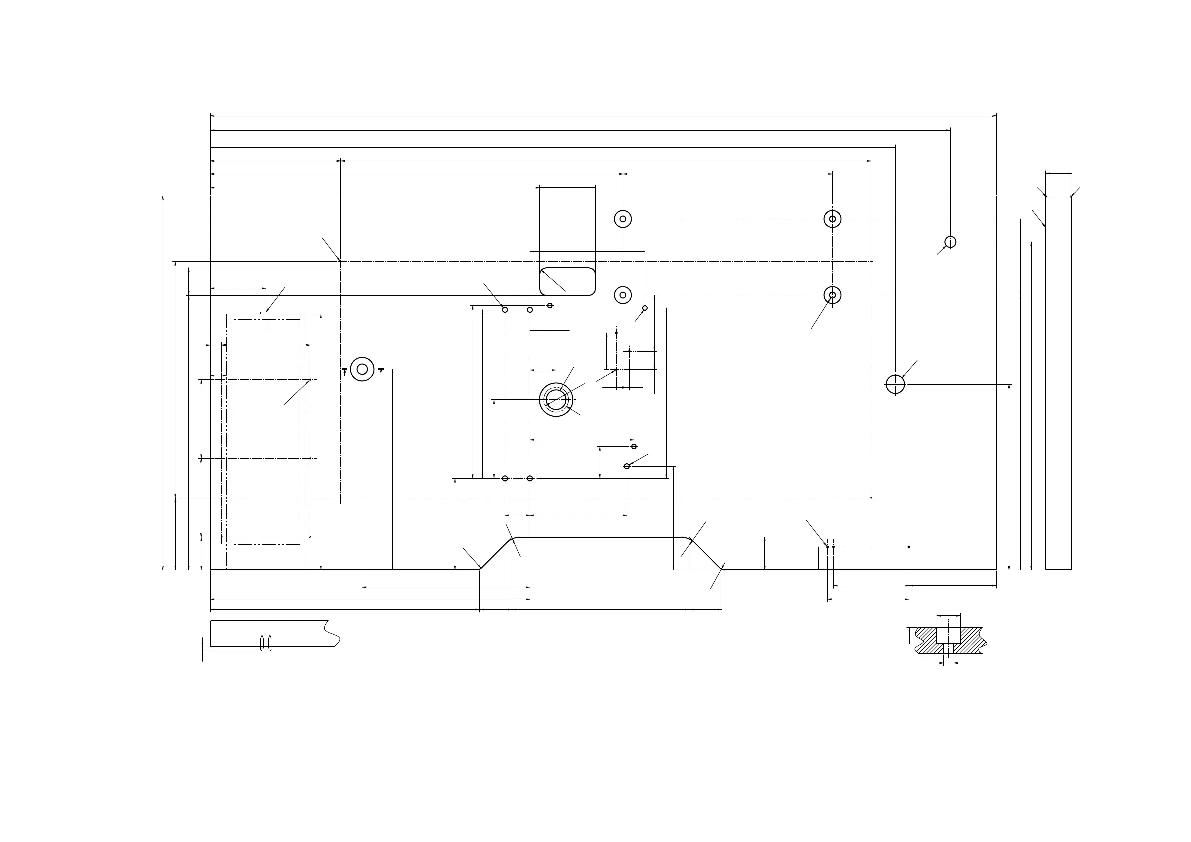
III. DRAWING OF THE TABLE
Longitudinal installation type table (Part No. 40143093)
4- drilled hole 2, 10 deep on the rear side (stand installing hole)
Drawer stopper installing position (one place on the rear side)
3- drilled hole 3, 10 deep on the rear side (pedal installing hole)
4- drilled hole 8
Drilled hole 30, 51 spot face 16 deep
Oil drain funnel installing hole
3- drilled hole 7, 6 deep
Drilled hole 8
4-drilled hole 9, 26 spot face 1 deep
3-drilled hole 3, 10 deep on the rear side (power switch installing hole)
Drilled hole 17
Drilled hole 28
R2 (all corners)
Right side
6- drilled hole 3, 10 deep on the rear side (drawer installing hole)
ZZ
42
500
570
199
1130
1200
411
50 50
133.5
418.5
110
283
270
40
Z-Z(1:2)
Ø
36
Ø
16
135
120
6
35
263.5
120
390
488
503
85
40
256
1046
85
25
30.5
R30
R30
R10
R10
50
38
Ø
25
10
50
85.7
56
±1
148
±0.5
630
±3
419 116
±4
257
±1
306
±1
139.5
±0.5
48.7
±1
259.8
±1
158
±0.5
360
±1
28
±0.5
120
10
320
±1
158.8
±1
115
±1
810
±1
38
±0.5
124
±1
175.6
±1
17.5
4×R10

 Loading...