ENGLISH
– 39 –
F1
F2
F1
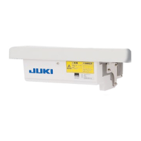
[ Replacing F1 fuse on CTL circuit board (solenoid protection fuse) ]
1) Loosen two setscrews in the front cover and
open the cover after checking that the power has
been turned OFF.
2)
Replace 5A F1 fuse on CTL circuit board with a
fuse of the same capacity supplied as accesso-
ries.
3)
Close the front cover as before and x it with the
setscrews while paying attention to pinching of
the cords.
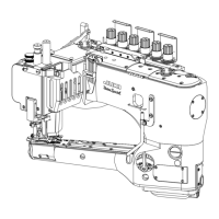
5) Replace 3.15A F1 fuse or 2A F2 fuse on PWR
circuit board with a fuse of the same capacity
supplied as accessories.
6)
Fix the bottom cover as before with the set-
screws, and press the front cover to the bottom
cover from the position where the front cover is
obliquely tilted by approximately 45 degrees for
assembling.
7) Attach the connectors and the ground wire which
have been removed.
8) Close the front cover as before and x it with the
setscrews while paying attention to pinching of
the cords.
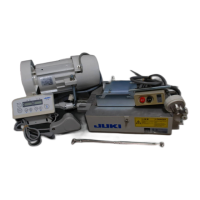
1) Loosen two setscrews in the front cover and
open the cover after checking that the power has
been turned OFF.
2)
Remove connectors CN30, CN32, CN33, CN36,
CN37 and CN38 and remove the setscrew at-
tached to the ground wire of CTL circuit board.
(Connector Nos. depend on the specications.)
3) Draw up the front cover obliquely at the position
where the front cover is obliquely tilted by ap-
proximately 45 degrees, and remove the cover.
Remove the control box from the motor.
4) Remove four setscrews in the bottom cover and
remove the bottom cover.
[ Replacing F1 fuse on PWR circuit board (power circuit protection fuse) ]
[ Replacing F2 fuse on PWR circuit board (regenerative resistance protection fuse) ]

 Loading...