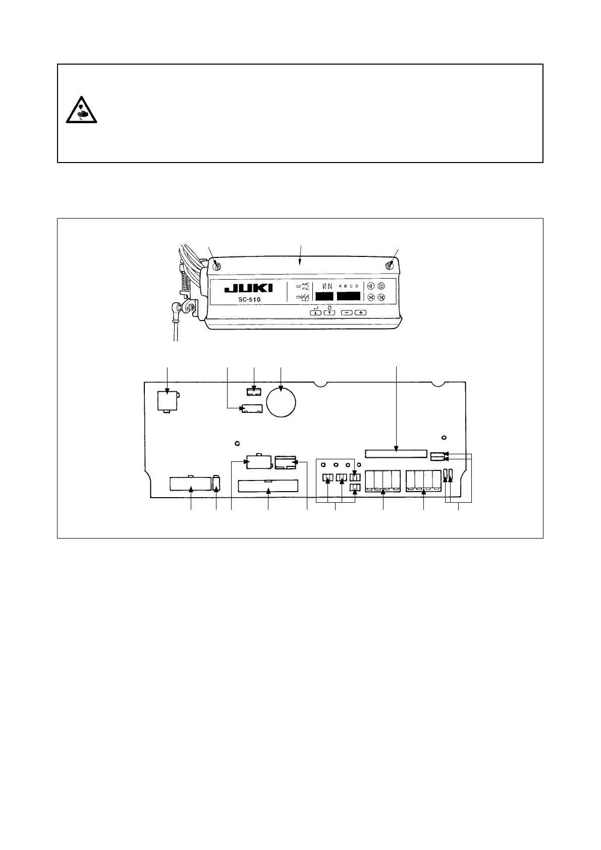
Following connectors are prepared when loosening the front cover xing screws
A
of SC-510 and opening
the cover. Connect the machine head connectors to the positions corresponding to each other so as to t the
devices mounted on the machine head.
6.
Connecting the cords
1
CN30 Motor signal connector
2
CN43 Needle bar position detector connector (+12V type)
3
CN32 Machine head connector
4
CN33 Needle bar position detector connector (+5V type)
5
CN36 Machine head solenoid connector
6
CN37 Presser foot lifter solenoid connector
7
CN38 CP-160 panel connector
8
CN40 Signal for extension output connector (For the details, refer to Engineer's Manual.)
9
W1, W2,
W3, W4
Optional jumper pins for changeover of input/output of power source
(For the details, refer to Engineer's Manual.)
!0
CN50 Optional output connector (For the details, refer to Engineer's Manual.)
!1
CN51 Optional input connector (For the details, refer to Engineer's Manual.)
!2
CN41 Connector for extension p.c.b. (For the details, refer to Engineer's Manual.)
!3
W5 to W8 Jumpers for optional input changeover (For the details, refer to Engineer's Manual.)
!4
CN39 Pedal for standing work connector (PK-70 and the like can be used.)
Front cover
A
A
9
2 31 4
5 7
!2
6 8
!1!0!4 !3
WARNING :
• To prevent personal injury caused by abrupt start of the sewing machine, carry out the work after
turning OFF the power switch and a lapse of 5 minutes or more.
• To prevent damage of device caused by maloperation and wrong specifications, be sure to
connect all the corresponding connectors to the specied places.
• To prevent personal injury caused by maloperation, be sure to lock the connector with lock.
• As for the details of handling respective devices, read carefully the Instruction Manuals supplied
with the devices before handling the devices.