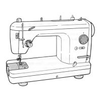
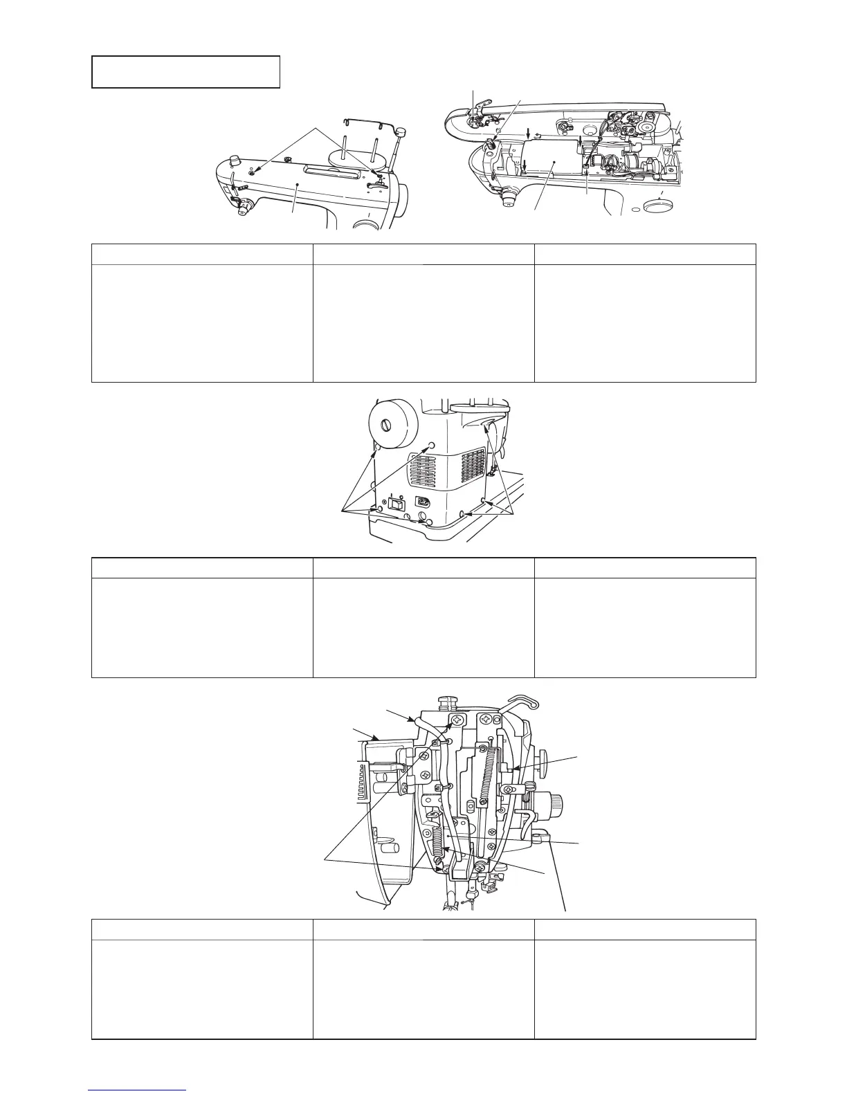
1. Arm cover asm.
3. Face plate asm.
Preparation
™
Remove arm cover.
2. Belt cover and motor cover
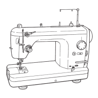
Outer Components
1
Arm cover setscrew
SM5042005SN
3
Arm cover
6
Convex of presser
spring regulator knob
5
Slit of presser regulating screw
3
Face plate asm.
1
Lamp connector
5
Face cover
2
Face plate asm. setscrew
SL5040631SE
6
Hand lifter lever spring
4
Indicating needle of
presser spring regulator
2
Motor cover setscrew
SM5041255SN
1
Belt cover setscrew
SM5041255SN
4
MAIN circuit
board case cover
2
Bobbin
winder
connector
Disassembly Assembly Point
™
Remove two
1
setscrews.
™
Disconnect and remove
2
con-
nector.
™
Insert
2
connector.
™
Align
6
convex with
5
slit and
tighten the setscrew.
™
There should be no torsion or
distorsion in presser spring regu-
lator.
™
Align precisely slit portion with
convex portion.
™
Do not press each lead wire.
Disassembly Assembly Point
™
Remove four
1
setscrews and
remove belt cover.
™
Remove three
2
setscrews and
remove motor cover.
™
Attach belt cover and tighten
1
setscrews.
™
Attach motor cover and tighten
2
setscrews.
™
There should be no difference
in level between belt cover and
front face of frame.
™
Make motor cover come closely
contact with belt cover.
Disassembly Assembly Point
™
Disconnect
1
connector and
6
remove.
™
Remove
2
setscrews and re-
move
3
face plate asm.
(together with face cover).
™
Attach
3
face plate asm., tighten
it with face plate asm.
2
set-
screws, and attach
6
hand lifter
lever spring.
™
Insert
1
connector.
™
There should be no difference in
level around the cover when face
cover is closed.
™
5
should not come in contact
with
4
indicating needle.
 Loading...