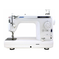
2. Handwheel and clutch
Preparation
™
Remove belt cover.
™
Remove arm cover.
9
Motor pulley
6
Groove of
handwheel bushing
8
Handwheel bushing stopper pin
4
Angle portion of clutch spring
7
Convex of handwheel bushing
3
Groove of clutch spring support
!0
Groove of handwheel
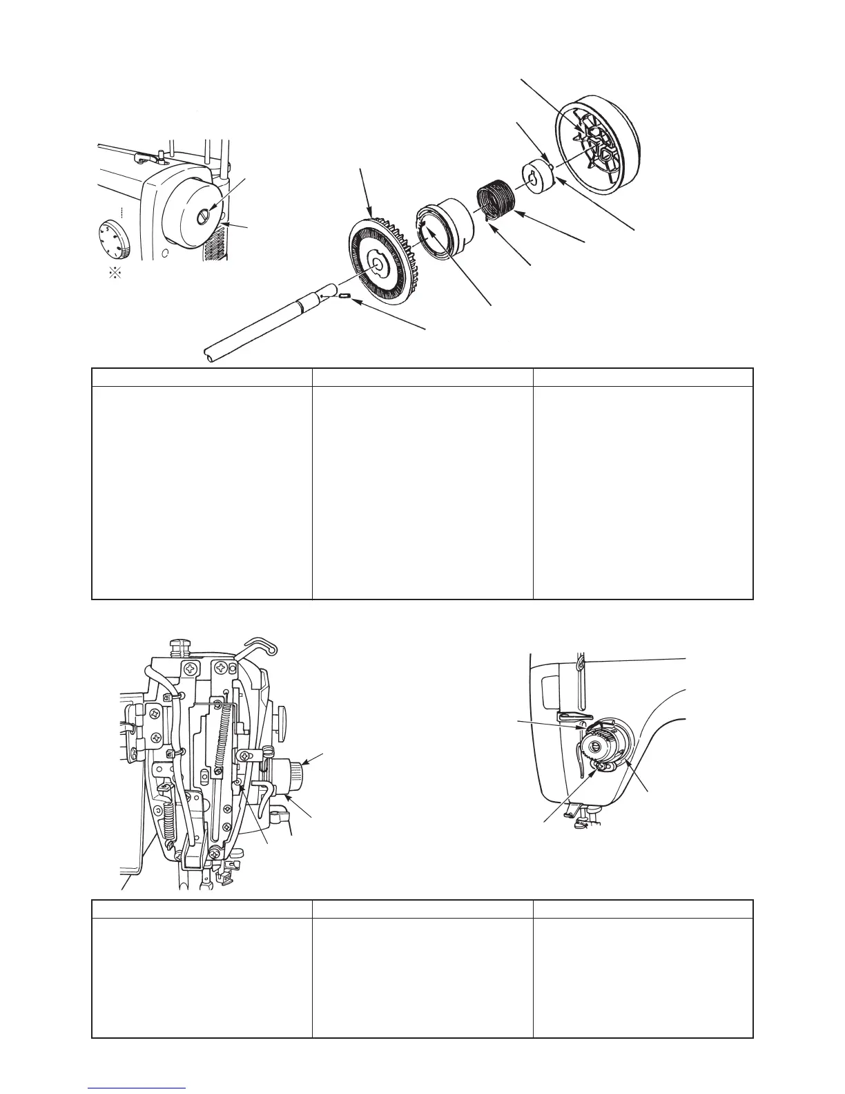
3. Thread tensioner asm.
Disassembly
™
Remove
1
setscrew.
™
Remove cord guide plate set-
screw and remove cord guide
plate asm.
™
Remove
3
spring support.
™
Move
4
in the direction where
clutch spring is released and re-
move clutch spring.
™
Face
6
to motor side and
8
is
hard to drop.
™
Draw out
8
and remove
9
.
Assembly
™
Attach
9
and enter
8
.
™
Enter
6
groove of bushing to
8
stopper pin and attach bushing.
™
Enter
5
hook portion of spring
to slit in the center of handwheel
bushing
™
E n t e r
5
c l u tc h s p r i n g t o
3
groove of spring support and at-
tach cord guide plate asm. Then
tighten setscrew.
Point
™
Align
7
convex of bushing with
!0
groove of handwheel and at-
tach handwheel. Then tighten
setscrew.
™
Clearance provided between con-
vex of
3
clutch spring support
and clutch plate is 2 ± 0.5 mm.
™
See item 12 on page 19 for ad-
justment.
1
Handwheel
setscrew
2
Handwheel
Disassembly
™
Remove
1
setscrew.
™
Lower presser foot and remove
2
setscrew.
™
Remove
3
spring together with
4
thread tensioner asm. and ad-
justing plate.
Assembly
™
Attach
6
adjusting plate and
3
spring to thread tensioner asm.
and attach it to frame. Then x it
with
2
setscrew.
™
Tighten
1
adjusting plate set-
screw.
Point
™
Place upward the scale of
5
thread tension disk presser.
™
See items 9 and 10 on page 19
for adjustment of pressure and
thread take-up spring of stroke.
1
Thread take-up spring
adjusting plate setscrew
SL5030801SN
2
Thread tensioner setscrew
SM8040602TP
3
Thread take-up spring
4
Thread tensioner asm.
5
Thread tension disk presser
5
Hook portion of clutch spring
6
Thread take-up
spring adjusting
plate
When removing motor
pulley, remove cord guide
plate setscrews
5
and
5
-1
in previous item.
 Loading...