– 17 –
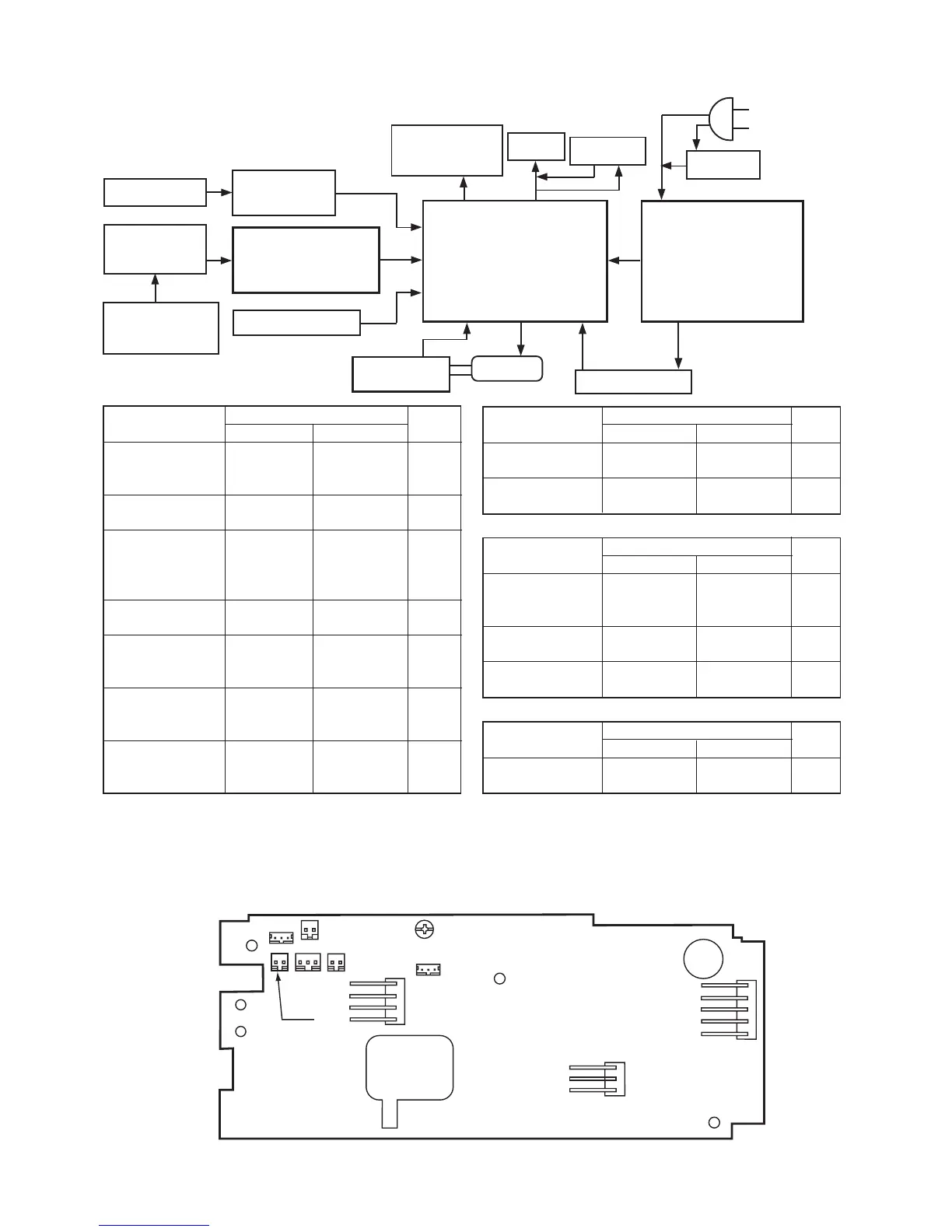
Description MAIN circuit board Cord
Terminal Pin color
Motor CN7 1 Blue
3 Brown
5 Black
Power connecting CN9 1 Blue
wire 2 Brown
Transformer CN8 1 Yellow
secondary side 2 Yellow
(AC 22V, 19.8V) 3 Red
4 Red
Lamp CN2 1 Gray
2 Gray
Bobbin winder SW CN1 1 Purple
2-
3 Gray
MP detection circuit CN6 1 Black
board 2 -
3 Red
Thread trimmer SW CN3 1 Orange
circuit board 2 -
3 Brown
(Caution) 1. CN Nos. in frame of MAIN circuit board denote connector Nos. in MAIN circuit board.
2. Portions enclosed with thick lines denote circuit boards.
3. Numerals outside of frame of MAIN circuit board denote number of lead wires.
Description MAIN circuit board Cord
Terminal Pin color
Controller socket CN5 1 Yellow
2 White
Thread trimmer CN4 1 Blue
solenoid (TL-98Q) 2 Blue
CN1
CN2
CN4
CN3
CN5
CN6
CN7
CN8
[4] PRINTED CIRCUIT BOARD DIAGRAM (CONNECTOR LAYOUT)
Description FILTER circuit board Cord
Terminal Pin color
Transformer Primary CN21 1 White
side (AC 120V) 2 Blue
Power connecting CN22 1 Brown
wire 2 Blue
Power input CN23 1 Blue
(AC 120V) 2 Yellow
Description Cord
Terminal Pin color
External thread CN11 1 Black
trimmer socket 2 Brown
2
(AC 22V),
(AC19.8V)
Controller
Thread trimmer
socket
(TL-98Q)
External thread
trimmer SW
(TL-98Q)
Controller
socket
Bobbin winder SW
Thread trimmer
solenoid
(TL-98Q)
Lamp SW
FILTER
circuit board
Power SW
Motor
MP detection
circuit board
MAIN circuit board
Lamp
CN11
Thread trimmer
SW circuit board
3
3
2
33
2
2
2
4
2
CN5
CN3
CN7
CN1
CN6
CN2
CN8
CN4
CN9
2
2
Transformer
CN22
2
CN21
CN23
AC120V(TL-98Q)
AC120V (TL-98Q)
Plug socket
(MAIN circuit board)
CN9
Thread trimmer SW circuit board