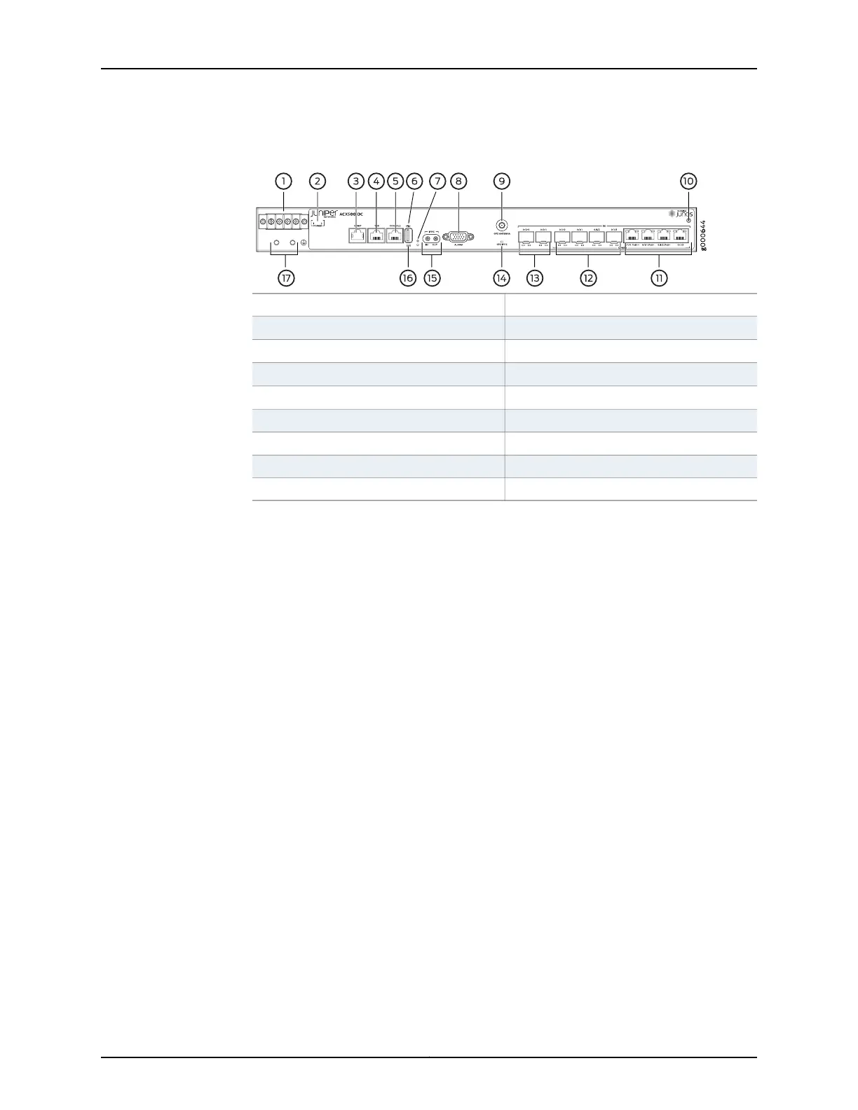
Figure 2: Front Panel of the DC-Powered ACX500 Indoor Router
10—1— ESD pointDC terminals
11—2—
Gigabit Ethernet RJ-45 ports (COMBO)
DC power status LED
12—3—
Gigabit Ethernet SFP ports (COMBO)
Management Ethernet port
13—4— Gigabit Ethernet SFP ports
Time of day (TOD) RJ-45 port
14—5—
GPS LED (GPS 1PPS)
Console port
15—6— External clocking portsUSB port
16—7—
System status LED (SYS)
Recovery switch
17—8— Grounding terminalsAlarm contact port
9—GPS antenna port
5
ACX500 Routers Quick Start Description
 Loading...