1. Attach the electrostatic discharge (ESD) grounding strap to your bare wrist, and
connect the strap to the ESD point on the chassis.
2. Ensure that the power supplies are fully inserted in the chassis and the screws
on their faceplates are tightened.
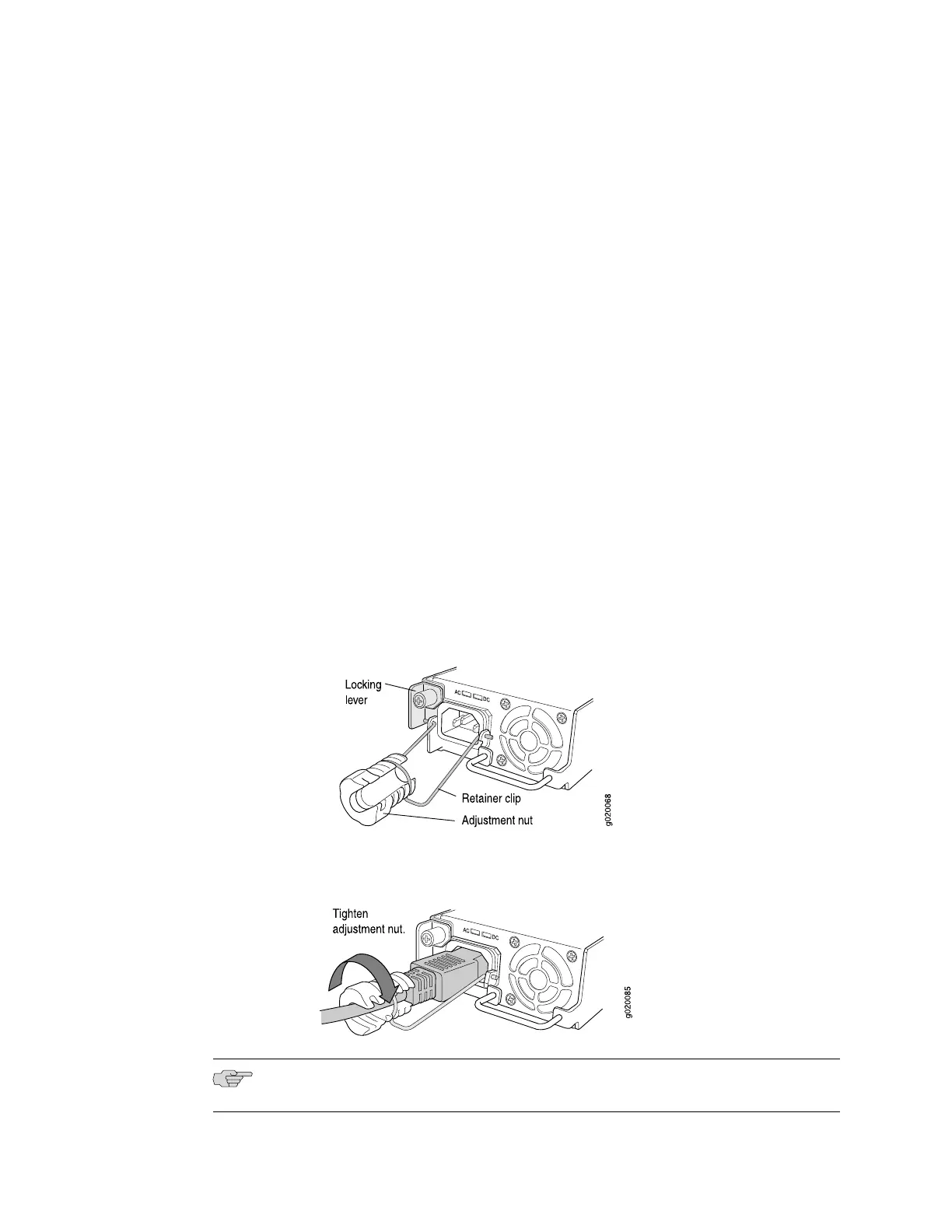
3. Squeeze the two sides of the power cord retainer clip, and insert the L-shaped
ends of the wire clip into the holes in the bracket on each side of the AC appliance
inlet on the AC power supply faceplate (see Figure 1 on page 2).
4. Locate the power cord or cords shipped with the switch; the cords have plugs
appropriate for your geographical location. See AC Power, Connection, and Power
Cord Specifications—EX 3200 and EX 4200 Switches.
5. Insert the coupler end of the power cord into the AC appliance inlet on the AC
power supply faceplate.
6. Push the cord into the slot in the adjustment nut of the power cord retainer. Turn
the nut until it is tight against the base of the coupler and the slot in the nut is
turned 90° from the top of the switch (see Figure 2 on page 2).
7. If the AC power source outlet has a power switch, set it to the OFF (0) position.
8. Insert the power cord plug into an AC power source outlet.
9. If the AC power source outlet has a power switch, set it to the ON (|) position.
10.
Verify that the AC OK LED on the power supply is lit and is on steadily.
Figure 1: Connecting the AC Power Cord Retainer Clip to an AC Power Supply in an
EX 3200 or EX 4200 Switch
Figure 2: Connecting an AC Power Cord to an AC Power Supply in an EX 3200 or
EX 4200 Switch
NOTE: Each power supply must be connected to a dedicated power source outlet.
2 ■ Connecting AC Power to an EX-series Switch
 Loading...