Step 4: Connect External Devices and Cables
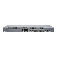
Figure 8: Routing Engine Ethernet Cable Connector
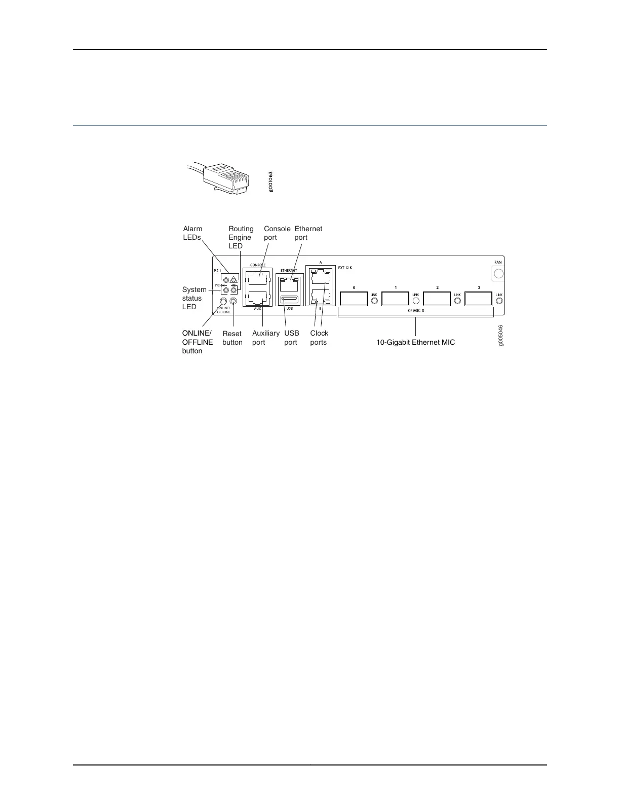
Figure 9: Front Panel Ports
g005046
ONLINE/
OFFLINE
Auxiliary
port
USB
port 10-Gigabit Ethernet MIC
Console
port
Ethernet
port
Clock
ports
Routing
Engine
LED
Alarm
LEDs
System
status
LED
Reset
button
ONLINE/
OFFLINE
button
•
Connect the MX5, MX10, MX40, or MX80 Router to a Network for Out-of-Band
Management on page 11
•
Connect the MX5, MX10, MX40, or MX80 Router to a Management Console or Auxiliary
Device on page 11
•
Connect MIC Cables to the MX5, MX10, MX40, or MX80 Router on page 11
Connect the MX5, MX10, MX40, or MX80 Router to a Network for Out-of-Band Management
1. Turn off the power to the management device.
2. Plug one end of the Ethernet cable (Figure 8 on page 11 shows the connector) into
the ETHERNET port on the Routing Engine. Figure 9 on page 11 shows the port.
3. Plug the other end of the cable into the network device.
Connect the MX5, MX10, MX40, or MX80 Router to a Management Console or Auxiliary Device
1. Turn off the power to the console or auxiliary device.
2. Plug the RJ-45 end of the serial cable (Figure 8 on page 11 shows the connector) into
the AUX port or CONSOLE port on the front panel. Figure 9 on page 11 shows the ports.
3. Plug the female DB-9 end into the device's serial port.
Connect MIC Cables to the MX5, MX10, MX40, or MX80 Router
1. Have ready a length of the type of cable used by the component. For MIC cable
specifications, see the MX Series Interface Module Reference.
2. Remove the rubber safety plug from the cable connector port.
11Copyright © 2015, Juniper Networks, Inc.
Step 4: Connect External Devices and Cables

 Loading...