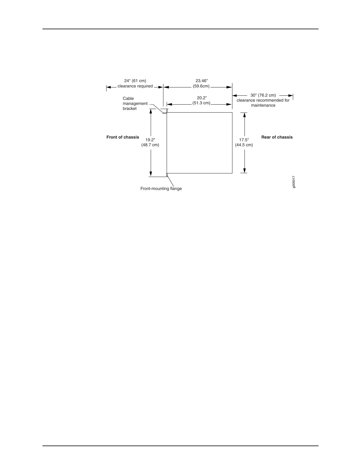
Figure 1: MX5, MX10, MX40, and MX80 Rack Clearance and Router
Dimensions
Rear of chassis
Front of chassis
17.5"
(44.5 cm)
20.2"
(51.3 cm)
g005017
Front-mounting flange
19.2"
(48.7 cm)
24" (61 cm)
clearance required
30" (76.2 cm)
clearance recommended for
maintenance
Cable
management
bracket
23.46"
(59.6cm)
Tools Required to Prepare the MX5, MX10, MX40, and MX80 Router for Installation
•
Blank panels to cover any slots not occupied by a component
•
Mounting brackets, supplied with the router
•
Eight screws for securing the mounting brackets to the chassis, supplied with the router
•
Phillips (+) screwdriver, number 2
Move the Mounting Brackets for Center-Mounting the MX5, MX10, MX40, or MX80 Router, If
Needed
Two removable mounting brackets are attached to the mounting holes closest to the
front of the chassis (see Figure 2 on page 6). You can move the pair of brackets to
another position on the side of the chassis for center-mounting the router.
To move the mounting brackets from the front of the chassis toward the center of the
chassis (see Figure 3 on page 6):
1. Remove the four screws at the top and bottom of the bracket.
2. Pull the bracket away from the chassis.
3. Align the bracket with the two sets of mounting holes located toward the center of
the chassis.
4. Insert the four screws at the top and bottom of the bracket and tighten each partially.
5. Tighten the four screws completely.
6. Repeat the procedure for the other bracket.
5Copyright © 2015, Juniper Networks, Inc.
Tools Required to Prepare the MX5, MX10, MX40, and MX80 Router for Installation

 Loading...