(No.PA056<Rev.002>) 15
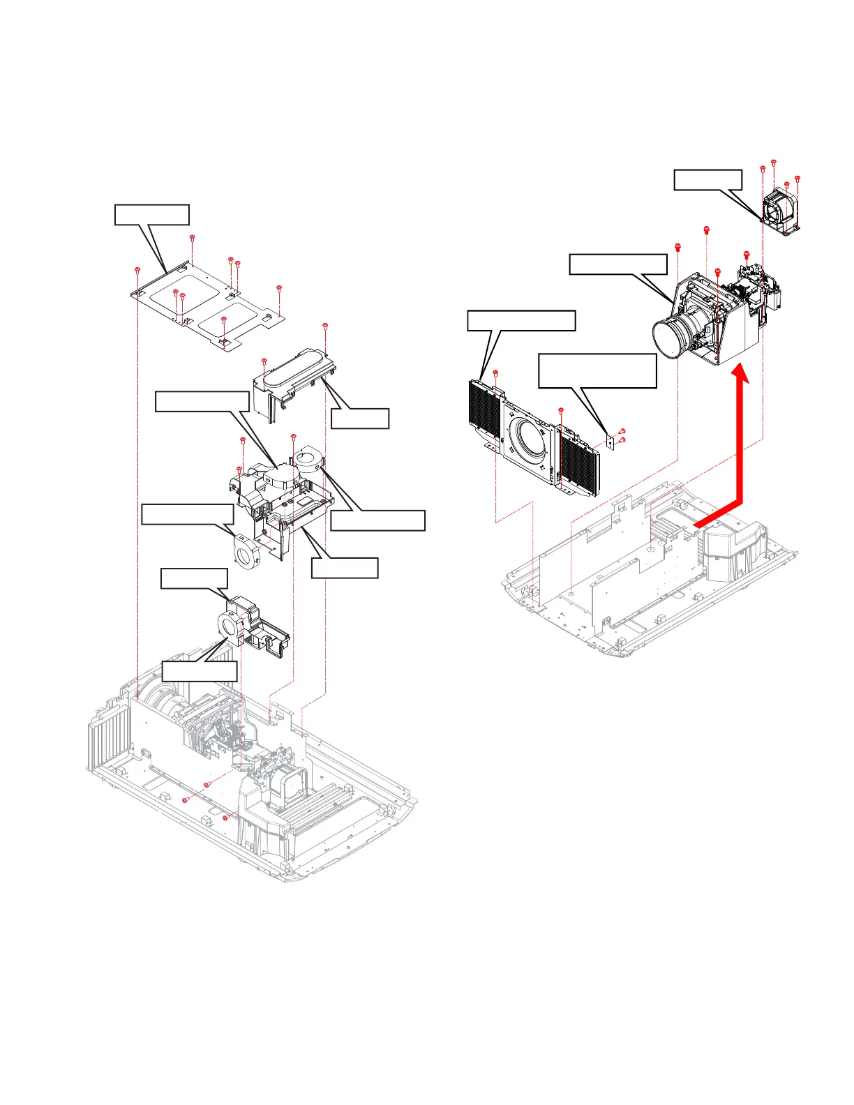
3.2.8 Remove the INTERLOCK PWB and OPTICAL UNIT
(Fig.3-9 and Fig.3-10)
(1) Remove the 8 screws (a), and remove the BRACKET.
(2) Remove the 2 screws (b), and remove the COVER.
(3) Remove the DEVICE COOLING FAN.
(4) Remove 3 screws (c), and remove the DUCT-1.
(5) Remove the DEVICE COOLING FAN.
(6) Remove 3 screws (d), and the REMOVE DUCT-2.
(7) Remove the OP COOLING FAN.
Fig.3-9
(8) Remove the 2 screws (a), and remove the FRONT PLATE.
(9) Remove the 2 screws (b), and remove the INTERLOCK
PWB (for the FONT COVER).
(10) Remove 4 screws (c), and remove the OP BASE.
(11) Remove the 4 screws (d), and remove the OPTICAL UNIT.
Fig.3-10
BRACKET
COVER
DUCT-1
R DEVICE COOLING FAN
OP COOLING FAN
a
a
a
a
a
a
a
a
b
c
c
d
d
d
c
b
DUCT-2
B DEVICE COOLING FAN
G DEVICE COOLING FAN
FRONT PLATE
OPTICAL UNIT
OP BASE
a
a
b
b
d
d
d
d
c
c
c
c
INTERLOCK PWB
(for the FONT COVER)
 Loading...