(No.PA048<Rev.002>)1-13
SECTION 3
DISASSEMBLY
3.1 CAUTION AT DISASSEMBLY
• Make sure that the power cord is disconnected from the outlet.
• Pay special attention not to break or damage the parts.
• Make sure that there is no bent or stain on the connectors before inserting, and firmly insert the connectors.
• Be sure to reattach the wire clamps removed during the procedure to the original positions. (Attaching the wire clamps in wrong
positions may affect the performance.)
REFERENCE:
When removing each board, remove the connector if necessary. The operation is easier if you write down the connection points
(connector numbers) of the connector. For connection of each board, refer to the "WIRING DIAGRAM" of the Standard Circuit
Diagram.
3.2 DISASSEMBLY PROCEDURE
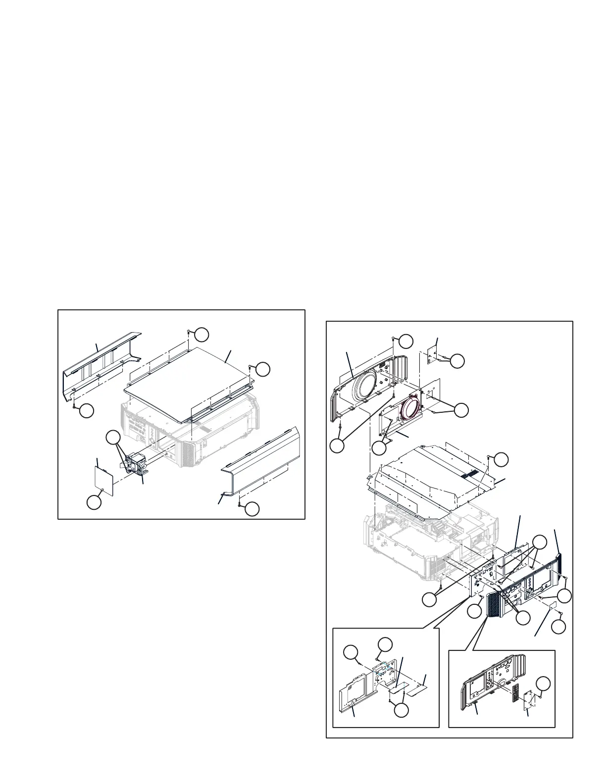
3.2.1 REMOVING THE LAMP UNIT (Fig.3-1)
(1) Loosen the 1 screw [A], then remove the LAMP DOOR.
(2) Loosen the 2 screws [B], then remove the LAMP UNIT.
3.2.2 REMOVING THE SIDE PANEL (Fig.3-1)
(1) Remove the 6 screws [C], then remove the SIDE PANEL.
3.2.3 REMOVING THE TOP CABINET (Fig.3-1)
(1) Remove the 8 screws [D], then remove the TOP CABINET.
Fig.3-1
3.2.4 REMOVING THE REAR PANEL (Fig.3-2)
(1) Remove the 1 screw [A], then remove the BLIND SW
HOLE.
(2) Remove the 2 screws [B] and 2 screws [C], then remove
the REAR PANEL.
3.2.5 REMOVING THE KEYPAD PWB (Fig.3-2)
(1) Remove the 3 screws [D], then remove the KEYPAD PWB.
3.2.6 REMOVING THE SHIELD TOP (Fig.3-2)
(1) Remove the 14 screws [E], then remove the SHIELD TOP.
3.2.7 REMOVING THE SHIELD REAR (Fig.3-2)
(1) Remove the 4 screws [F] and 2 screws [G], then remove
the SHIELD REAR.
3.2.8 REMOVING THE TERMINAL-1 PWB (Fig.3-2)
(1) Remove the 2 screws [H] and 2 screws [J], then remove
the TERMINAL-1 PWB.
3.2.9 REMOVING THE TERMINAL-2 PWB (Fig.3-2)
(1) Remove the 2 screws [K], then remove the TERMINAL-1
PWB.
3.2.10 REMOVING THE FRONT PANEL (Fig.3-2)
(1) Remove the 2 screws [L], then remove the FRONT PAN-
EL.
3.2.11 REMOVING THE LENS COVER ASSY (Fig.3-2)
(1) Remove the 4 screws [M], then remove the LENS COVER
ASSY.
3.2.12 REMOVING THE LED&IR PWB (Fig.3-2)
(1) Remove the 2 screws [N], then remove the LED&IR PWB.
Fig.3-2
SIDE PANEL
LAMP DOOR
LAMP UNIT
SIDE PANEL
TOP CABINET
CC
CC
BB
DD
DD
AA
FRONT PANEL
REAR PANEL
REAR PANEL
KEYPAD PWB
TERMINAL-1 PWB
TERMINAL-2 PWB
BLIND SW HOLE
LENS COVER ASSY
LED&IR PWB
SHIELD TOP
SHIELD REAR
SHIELD REAR
EE
EE
AA
FF
DD
CC
NN
MM
MM
LL
BB
HH
KK
JJ
FF
GG
 Loading...