1-18 (No.PA048<Rev.002>)
SECTION 4
ADJUSTMENT
4.1 BEFORE STARTING ADJUSTMENT
(1) Adjustment items utilize a personal computer.
(2) Data back up is required before adjustments.
(3) Allow the equipment and test instruments adequate time (at least 10 minutes) to warm-up.
(4) Confirm the set is properly connected to the specified AC power source.
(5) Use care not to disturb internal controls and parts not specifically mentioned.
(6) Unless specifically mentioned in the "ADJUSTMENT" steps, do not change any data.
4.2 INSTRUMENTS AND TOOLS
• Oscilloscope
• Light meter [for example: Minolta T-10]
• Color-meter [CL-200]
• PC (WINDOWS machine, with NET Framework 4.0 installed)
• Adjustment software
• RS-232C 9pin NULL-MODEM (cross) cable
• USB cable
•LAN cable
• Photoelectric conversion device (one of these)
Light meter [Minolta T-10] A-out (Analog output)
•Screen
• Darkroom (illumination less than 0.03 lx)
4.3 REQUIRED ADJUSTMENTS BY REPLACING COMPONENTS
The following adjustment procedure is required after replacing PWB ASS'Ys and OPTICAL BLOCK.
4.3.1 COMPONENT REQUIRED ADJUSTMENT AT REPLACING
*1: If the EEPROM Backup is not possible.
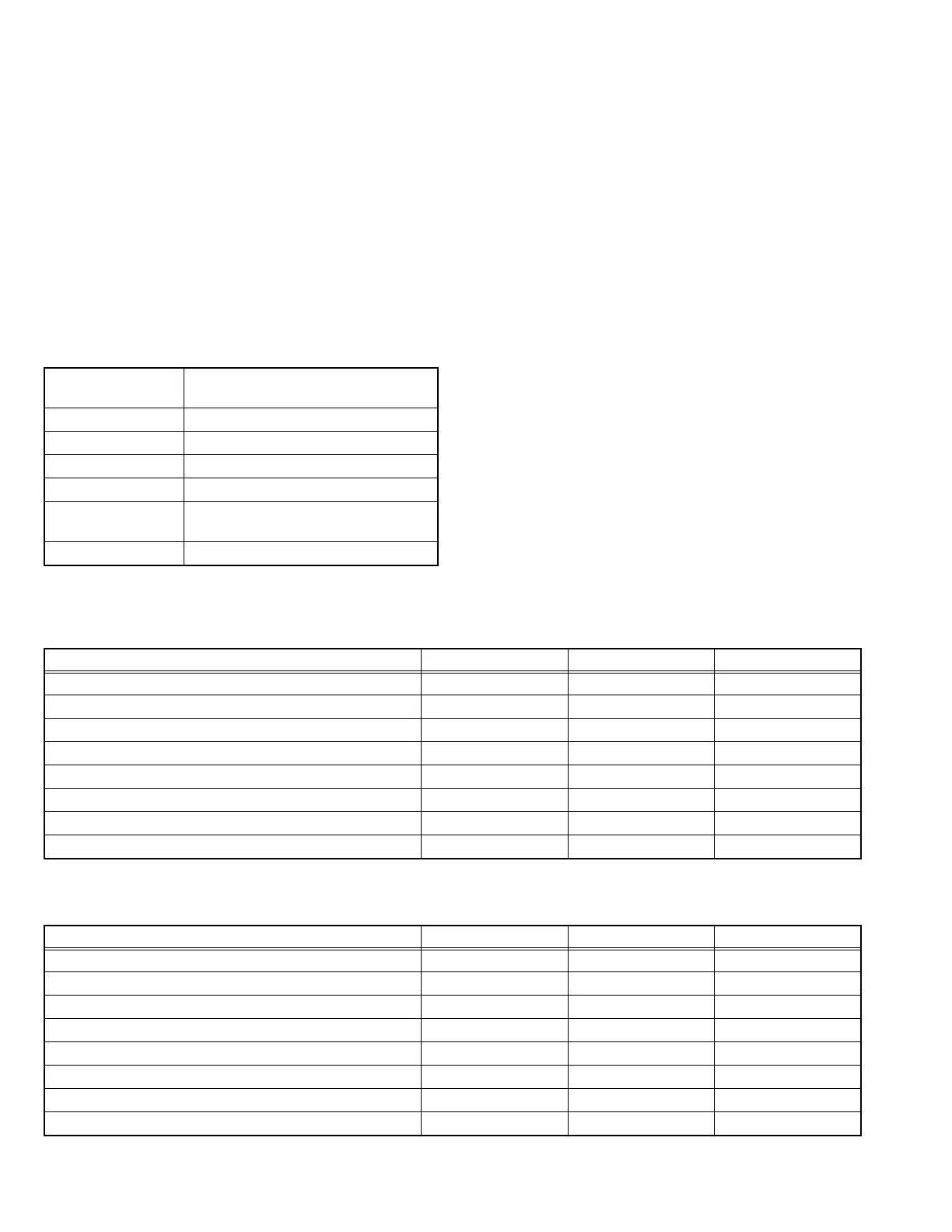
4.3.2 LIST OF REQUIRED INSTRUMENTS AND TOOLS
Operating system Windows XP(SP3) / VISTA / 7 (Only En-
glish)
Memory More than 16 Mbytes
Hard disk free space More than 5 Mbytes
RS-232C interface At least 1 port
Display resolution Minimum : 800 × 600 pixels
Display colors Minimum : 8 bits/pixel
Recommended : 16 bits/pixel or better
Input devices Keyboard and mouse
Adjustment items PROCESSOR PWB OPTICAL BLOCK DD SUB PWB
Main EEPROM Backup z
Model code Writing z
Destination Writing z
Transferring CMS Data From DD SUB PWB zz
Data Backup of DD SUB PWB z
Pixel Shift z
Lens Position Reset z
MAC address Writing z*1
Adjustment items PC Screen Signal Generator
Main EEPROM Backup z
Model code Writing z
Destination Writing z
Transferring CMS Data From DD SUB PWB zz
Data Backup of DD SUB PWB zz
Pixel Shift zz
Lens Position Reset z
MAC address Writing z
 Loading...